background image

16

en | Appendix

1200 Series IP Video Storage System

DOC | V1 | 2010.08

Installation Manual

Bosch Sicherheitssysteme GmbH

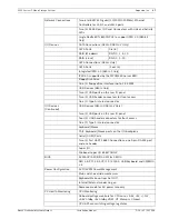
Motherboard Features

34

Floppy

Floppy Disk Drive connector

5

JAR

Alarm Reset

30

JD1

Speaker header (Pins 3/4: Internal, 1~4:External)

28

JF1

Front Panel Control header

41

JL1 

Chassis Intrusion header

29

JLED

Power LED Indicator header

37

JPW1

24-pin ATX main power connector (required)

36

JPW2

+12V 8-pin CPU power connector (required)

1

KB/Mouse

Keyboard/mouse connectors

8,9

LAN1~LAN2, 

Gigabit Ethernet (RJ45) ports (LAN1/LAN2)

21

I-SATA 0~5

Serial ATA ports (X8SIL has 4 Serial ATA Ports)

2

IPMI

IPMI LAN Port (X8SIL-F Only)

35

JPI2C

PWR supply (I2C) System Management Bus 

31

SPKR1

Internal speaker/buzzer

25

T-SGPIO-0/1

Serial General Purpose IO headers (for SATA)

3,20

USB0/1, USB 2/3

Backplane USB 0/1, Front panel accessible USB 2/

3

19

USB 4

Type A USB Connector

18

USB 10/11

Front Panel USB header (X8SIL-F Only)

22

DOM PWR

Disk-On-Module (DOM) Power Connector

39

JTPM

Trusted Platform Module (TPM) Header

6

VGA

Onboard Video Port

X8SIL/X8SIL-F/X8SIL-V LED Indicators

Number

LED

Description

Color/State

Status

26

LE4

Onboard Standby PWR LED 

Green: Solid on

PWR On

15

LE7

IPMI Heartbeat LED (X8SIL-F 

Yellow: Blinking

IPMI: Normal

CPU

Single Intel Xeon 3400 series processor in an LGA1156 socket.

Memory 

Four (4) 240-pin, DDR3 SDRAM DIMM sockets with support for 

up to 16GB of UDIMM or up to 32GB of RDIMM memory (ECC/

DDR3 1333/1066/800 MHz memory only.) 

Supports dual-channel memory bus

DIMM sizes

UDIMM

1 GB, 2 GB, and 4GB

RDIMM

1 GB, 2GB, 4GB, and 8GB

Chipset 

Intel 3420 Chipset (X8SIL-F/X8SIL-V)

Intel 3400 Chipset (X8SIL)

Expansion Slots 

Two (2) PCI Express 2.0 (x8) slot

One (1) PCI Express x4 (x8) slot

One (1) 32-bit PCI 33MHz slot

Integrated Graphics

Matrox G200eW

Summary of Contents for 1400 Series

Page 1: ...1200 Series IP Video Storage System en Installation Manual ...

Page 2: ......

Page 3: ...erface 7 3 1 Control Panel Buttons 7 3 2 Control Panel LEDs 7 4 Installation 9 5 Chassis Setup and Maintenance 10 5 1 Removing the Chassis Cover 10 5 2 Rotating the Hard Drive Cage 11 5 3 Removing and Installing Hard Drives 11 5 4 Installing the I O Shield and Motherboard 13 5 5 Installing the System Fan 13 5 6 Power Supply 13 A Appendix 14 A 1 Motherboard layout 14 A 2 Chipset Overview 19 A 3 PC ...

Page 4: ...tlet If an electrical accident occurs you can then quickly remove power from the system Do not work alone when working with high voltage components Power should always be disconnected from the system when removing or installing main system components such as the serverboard memory modules and optical device drives When disconnecting the power you should first power down the system with the operati...

Page 5: ... 1 6 System Safety Electrostatic discharge ESD is generated by two objects with different electrical charges coming into contact with each other An electrical discharge is created to neutralize this difference which can damage electronic components and printed circuit boards The following measures are generally sufficient to neutralize this difference before contact is made to protect your equipme...

Page 6: ... or screws The chassis is equipped with high efficiency power supply High performance fans provide ample optimized cooling for FB DIMM memory modules and four hot swap drive bays offer maximum storage capacity For information on supported hardware see the datasheet for the 1200 Series in the Bosch Online Product Catalog For more detailed technical information on your device refer to http www super...

Page 7: ...you may need to take 3 1 Control Panel Buttons Power The main power button is used to apply or remove power from the power supply to the system When the power is on the power button will be lighted by a blue LED Turning off the system power with this button will cause the blue LED to turn off and will remove the main power but will keep standby power supplied to the system Therefore you must unplu...

Page 8: ...When Continuously On not flashing This LED indicates an overheat condition caused by cables obstructing the airflow in the system or the ambient room temperature being too warm Correcting an Overheat Fan Fail Condition 1 Check the routing of the cables and move any cables the restrict airflow 2 Confirm that all fans are operating normally 3 Verify that the heatsinks are installed properly 4 If the...

Page 9: ... en 9 Bosch Sicherheitssysteme GmbH Installation Manual DOC V1 2010 08 4 Installation The systems comes pre installed and only hard drives may be exchanged onsite In case of any other failure the entire system has to be exchanged by advanced exhange ...

Page 10: ...ngs and precautions listed in the manual before setting up or servicing this chassis These include information in Chapter System Safety and the warning precautions listed in the setup instructions 5 1 Removing the Chassis Cover Removing the Chassis Cover 1 Push the power button to turn off the power to the system 2 Disconnect the chassis from any power source 3 Slide the release tab A towards the ...

Page 11: ...onnect the chassis from any power source 2 Lift the release tab A 3 Rotate the hard disk drive cage B outward 5 3 Removing and Installing Hard Drives The 1200 Series chassis must be powered down before hard drives can be removed from the hard drive carriers Removing and Installing Hard Drives 1 Disconnect the chassis from any power source 2 Rotate the hard drive cage outward 90 degrees as describe...

Page 12: ... hard drive cage 6 If a hard drive is already present remove it by carefully pulling the sides of the hard drive carrier outward 7 Remove the hard drive from the hard drive carrier 8 Insert the new hard drive into the hard drive carrier 9 Insert the hard drive carrier into the hard drive cage sliding it towards the back of the the hard drive cage until it clicks into a locked position ...

Page 13: ... I O Shield and Motherboard Motherboard problems will be handled by trained support people only 5 5 Installing the System Fan System fan problems will be handled by trained support people only If the system fan has to be replaced the entire unit will be exchanged advanced exchange service Note The fan noise of the system is a factor to note When it occurs this can be an indication of impending fai...

Page 14: ...IO1 T SGPIO2 J24 JLAN2 JLAN1 SPKR1 JBT1 1 JI2C1 1 JI2C2 1 LE4 LE2 LE3 LE7 JPT1 1 JPB JLED1 1 1 JPUSB1 1 JPL1 1 JPL2 JPG1 JD1 1 FAN2 FAN1 FAN5 1 FAN4 FAN3 J16 PCI1 U2 BAR CODE 1 2 ENABLE 2 3 DISABLE JPL2 LAN2 JPL1 LAN1 2 3 DISABLE 1 2 ENABLE JPB BMC JPI2C PWR I2C JD1 Buzzer Speaker COM2 FLOPPY DDR3 1066 1333 UDIMM RDIMM required VGA COM1 USB4 JBT1 CMOS CLEAR SLOT7 PCI E X8 GEN2 JPT1 TPM JL1 LAN1 JP...

Page 15: ... JBT1 CMOS Clear 40 JPES Energy Saving Feature Pins 2 3 Disabled 13 14 JI2C1 JI2C2 SMB to PCI Slots 17 JPG1 Onboard VGA Enable Pins 1 2 Enabled 11 12 JPL1 JPL2 LAN1 LAN2 Enable Pins 1 2 Enabled 24 JPT1 TPM Enable Pins 1 2 Enabled 10 JPB BMC Jumper Pins 1 2 Enabled X8SIL X8SIL F X8SIL V Headers Connectors Number Connector Description 4 16 COM1 COM2 COM1 2 Serial connection headers 33 32 27 23 7 Fan...

Page 16: ... USB0 1 USB 2 3 Backplane USB 0 1 Front panel accessible USB 2 3 19 USB 4 Type A USB Connector 18 USB 10 11 Front Panel USB header X8SIL F Only 22 DOM PWR Disk On Module DOM Power Connector 39 JTPM Trusted Platform Module TPM Header 6 VGA Onboard Video Port X8SIL X8SIL F X8SIL V LED Indicators Number LED Description Color State Status 26 LE4 Onboard Standby PWR LED Green Solid on PWR On 15 LE7 IPM...

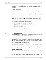
Page 17: ...he rear IO panel Two 2 USB header connectors for front access One 1 Type A internal connector I O Devices Continued USB Devices X8SIL F X8SIL V Only Two 2 USB ports on the rear IO panel Four 4 USB header connectors for front access One 1 Type A internal connector Keyboard Mouse PS 2 Keyboard Mouse ports on the I O backplane Serial COM Ports Two 2 Fast UART 16550 Connections one 9 pin RS 232 port a...

Page 18: ...lities BIOS flash upgrade utility Drivers and software for Intel 3400 3420 chipset utilities Other ROHS 6 6 Full Compliance Lead Free Dimensions Micro ATX form factor 9 6 x 9 6 Clarkdale IBexPeak BLOCK DIAGRAM DDR3 CHA Lynnfield PCIe2 0_x8 VRM 11 1 VID 0 7 RoHS 6 6 LPC I O W83627DHG PCIe x8 SLOT RJ45 RJ45 DDR3 CHB DIMM1 Far DIMM2 DIMM1 Far DIMM2 4 UDIMM MISC VRs 1333 1066MHz 1333 1066MHz 5 0Gb x4 ...

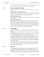
Page 19: ...hnology and Intel Rapid Storage Technology Dual NAND Interface Intel I O Virtualization VT d Support Intel Trusted Execution Technology Support PCI Express 2 0 Interface up to 5 0 GT s SATA Controller up to 3G s Advanced Host Controller Interface AHCI A 3 PC Health Monitoring This section describes the PC health monitoring features of the X8SIL X8SIL F X8SIL V These features are supported by an on...

Page 20: ...ard A 5 Power Supply As with all computer products a stable power source is necessary for proper and reliable operation It is even more important for processors that have high CPU clock rates of 1 GHz and faster The X8SIL X8SIL F X8SIL V accommodates ATX12V standard power supplies Although most power supplies generally meet the specifications required by the CPU some are inadequate A 2 Amp of curr...

Page 21: ...host servers Unlike fiber optic networks that require special cabling iSCSI can run over long distance using existing networks For the X8SIL X8SIL F X8SIL V motherboard iSCSI is supported on LAN 1 This can be enabled through the BIOS Advanced PCI PnP Configuration Onboard LAN1 Option ROM Select A 8 Overview of the Nuvoton BMC Controller The Nuvoton WPCM150 is a combined Baseboard Management Contro...

Page 22: ...22 en Appendix 1200 Series IP Video Storage System DOC V1 2010 08 Installation Manual Bosch Sicherheitssysteme GmbH ...

Page 23: ......
Page 24: ...Bosch Sicherheitssysteme GmbH Werner von Siemens Ring 10 85630 Grasbrunn Germany www boschsecurity com Bosch Sicherheitssysteme GmbH 2010 ...

Reviews: