background image


Appendix 59/64


3 842 358 792/2016-12, Material and information fl ow technology: HQ 2/C-H, HQ 4, 

Bosch Rexroth AG


17 Appendix

17.1 Function plans

On the following pages, you can fi nd proven fundamental function plans for control 

tasks in transfer systems. 

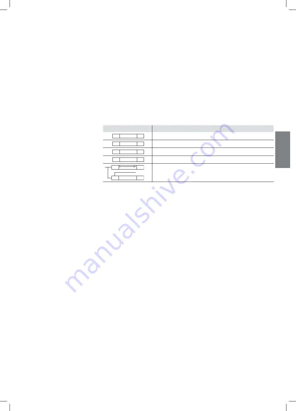
Contrary to DIN IEC 61131-3, qualifi ers are used in the action blocks, which are 

explained in the table below.

Simple VE 2 stop gates are used to stop the workpiece pallets. The position of the 

workpiece pallets is determined using separate proximity switches.

Action block

Explanation

S

Storing

NS

Non-storing

S

Set

R

Reset

T3

T3

?

NS

D

S

S           Y2.1

Non-storing triggering of a time function (with cycle time T). 
After it has been concluded, a switch function is triggered.

General abbreviations

WT

=

Workpiece pallet

VE

=

Stop gate

S … =

Signaling device

Y …

=

Valve

Z … =

Cylinder

LT

=

Longitudinal conveyor (main section)

QT

=

Transverse conveyor (adjacent section)

=

Start pulse after end of start-up

=

Release cyclic travel

EN

GLISH

551261_2016_12_EN.indd   59

551261_2016_12_EN.indd   59

22.12.2016   10:26:36

22.12.2016   10:26:36

Summary of Contents for 3 842 998 035

Page 1: ...uctions 3 842 358 792 2016 12 Replaces 2015 10 ENGLISH HQ 2 C H HQ 4 Lift transverse unit 3 842 999 002 3 842 998 035 ENGLISH 551261_2016_12_EN indd 1 551261_2016_12_EN indd 1 22 12 2016 10 26 35 22 12 2016 10 26 35 ...

Page 2: ...mo versión impresa print o como archivo PDF media para descargar del archivo de medios www boschrexroth com mediadirectory En el buscador en la parte superior derecha donde pone Search introduzca 3 842 358 795 a continuación haga clic en Search PT BR Este manual de montagem está disponível nos idiomas especificados aqui Outros idiomas mediante pedido Como versão impressa impressão ou como arquivo P...

Page 3: ...f HQ 2 C H or HQ 4 lift transverse unit 11 5 1 2 HQ 2 C H lift transverse unit features 11 5 2 Product description 12 5 3 Identification of the product 16 6 Transport and storage 16 6 1 Transporting the product 16 6 2 Storing the product 16 7 Assembly 17 7 1 Unpacking 17 7 2 Installation requirements 17 7 2 1 Installation position 17 7 2 2 Fastening with T bolts 17 7 3 Required tools 17 7 4 Symbols...

Page 4: ...re 42 10 2 Inspection 43 10 3 Maintenance 43 10 3 1 LU 2 automatic lubrication unit 44 10 4 Replacement of wear parts 45 10 4 1 Replacing the motor 46 10 4 2 Replacing the transmission external motor mounting 47 10 4 3 Replacing the transmission internal motor mounting 48 10 4 4 Replacing the chain 51 10 4 5 Spare parts 56 11 Decommissioning 56 12 Disassembly and replacement 56 12 1 Preparing the ...

Page 5: ...documentation Only start up the product if the documentation marked with the book symbol is available and you have understood and followed the instructions in it Table 1 Required and supplementary documentation Title Document number Document type Employee safety training 3 842 527 147 MTparts 3 842 529 770 Spare parts list on CD 1 3 Presentation of information Standardized safety instructions symb...

Page 6: ...dous situation that will result in serious injury or death if not avoided WARNING Indicates a hazardous situation that may result in severe injury or death if not avoided CAUTION Indicates a hazardous situation that may result in minor to moderate injury if not avoided NOTE Property damage The product or the surrounding area could be damaged 1 3 2 Symbols The following symbols indicate important i...

Page 7: ...The product is an incomplete machine It may be used as follows Installation in a Bosch Rexroth TS 2plus or TS 4plus transfer system Maximum load section load See technical data on page 58 Ambient conditions see page 58 The product is strictly intended for professional use and not for private use The intended use also implies that you have read all this documentation and fully understood it in part...

Page 8: ...try in which the product is being used Only use Rexroth products that are in good working order Heed all the notices on the product Persons who assemble operate disassemble or maintain Rexroth products should not be under the influence of alcohol drugs or medication that may affect their ability to react Use only original accessories and spare parts from Rexroth in order to prevent hazards to peopl...

Page 9: ...e authorized by the operator to be there This also applies while the product is at a standstill Make sure that there are no obstacles preventing access to the EMERGENCY STOP controls all delivery points workstations and passages are kept clear Do not use EMERGENCY STOP controls for routine stopping Regularly check the EMERGENCY STOP controls to ensure that they are functioning properly Following a...

Page 10: ...fer to the residual risks of the individual components see the section 8 2 Residual risks on page 38 Before initial commissioning make sure there are no protruding or sharp edged parts that may be a hazard to personnel working or moving in the area Provide safety related instructions to the operating personnel before initial start up or re commissioning and then in regular intervals 3 General note...

Page 11: ...s product 5 1 Specifications Fig 1 551 261 01 Q b b L Specifications for HQ 2 C H or HQ 4 lift transverse unit 5 1 1 Use of HQ 2 C H or HQ 4 lift transverse unit Installation in BS belt sections or ST sections Offset of height difference between main and transverse section to transfer workpiece pallets when Unloading from the main section Loading to the main section 5 1 2 HQ 2 C H lift transverse un...

Page 12: ... 2 U 1x G 2x FST 8 4 4x M8 x 16 4x M8 8x M8 x 20 8x 8 x M8 2 4x M8 4x 8x 8x M8 x 20 4x 2x 2x M8 8x M8 x 20 4x HQ 2 C H HQ 4 lift transverse unit shown 480 x 640 mm loading A Motor mounting M standard A1 Motor mounting R B Flat top chain C Damper kit DA 2 100 H loading shown D Mounting bracket 4x E Mounting kit F Lateral guide stop G Position monitoring kit Not included in delivery Damper kits shou...

Page 13: ...sable belt sections and section profiles Usable workpiece pallets HQ 2 C H 3 842 999 002 shown 480 x 640 mm Load up to 240 kg BS 2 BS 2 H ST 2 ST 2 H WT 2 WT 2 F WT 2 H WT 2 F H HQ 4 3 842 998 035 Load up to 250 kg BS 4 ST 4 WT 4 WT 4 F Observe the maximum section load see Section 16 Technical data on page 58 ENGLISH 551261_2016_12_EN indd 13 551261_2016_12_EN indd 13 22 12 2016 10 26 35 22 12 2016...

Page 14: ...erse unit is always the same as the direction of rotation of the motor Exception HQ 4 bT x bL 443 x 443 mm With these values the unloading HQ must be rotated by 180 when installed in order to transport the WT see Fig 4 This is the only way to ensure secure transport without the WT getting stuck 1 The customer must switch to motor mounting M on left see Section 7 5 Conversion to motor mounting M le...

Page 15: ... motor mounting Unloading Loading Reversible operation Fig 4 UM RS HQ BS ST HQ 4 443 x 443 AS BS ST UM BS ST RS HQ HQ 4 643 x 643 843 x 843 1043 x 1043 1243 x 1243 HQ 2 C H 640 x 640 800 x 800 1040 x 1040 1200 x 1200 AS BS ST Main direction of transport when bQ 443 x 443 mm or 480 x 480 mm ENGLISH 551261_2016_12_EN indd 15 551261_2016_12_EN indd 15 22 12 2016 10 26 35 22 12 2016 10 26 35 ...

Page 16: ... shipping documents for product weight Make sure the lifting straps are correctly fastened before lifting the product Secure the product to prevent it from toppling during lifting Make sure that no one but the operator is in the danger zone during lifting and lowering 6 2 Storing the product Only set the product down on a flat surface Protect the product from mechanical stress Protect the product f...

Page 17: ...he product level and plumb at right angles and axially parallel This ensures proper functioning and prevents premature wear 7 2 2 Fastening with T bolts Fasten the TS 1 TS 2plus TS 2pv TS 4plus and TS 5 transfer systems and the VarioFlow and VarioFlow S chain conveyor systems with T bolts and flange nuts Make sure the T bolt is in the correct position when inserting into the slot and tightening The...

Page 18: ...e Nm PH3 PZ2 Screwdrivers for cross head screws PZ Pozidriv screwdriver size PZ Phillips screwdriver size gleitmo 585 K Lubricate lubricate with specific grease lubricant Fuchs Lubritech gleitmo 585 K www fuchs lubritech com The marked parts are not required for the described assembly Dispose of the parts or use them for other purposes 2 1 3 Graphical depiction of mounting steps The numbers corresp...

Page 19: ...tor mounting M on left before installing the lift transverse unit A Motor mounting M standard right B Motor mounting M left customer conversion For removal of the power train see Section 10 4 3 Replacing the transmission internal motor mounting on page 48 Rotate the drive axis 180 before installation B The transmission will stay aligned Install the power train and belt section in reverse order of ...

Page 20: ... accessories Fastening kit for HQ 2 C H on BS 2 ST 2 included in delivery Fastening kit for HQ 4 on ST 4 R included in delivery 1 Mark the installation position of the mounting bracket 2 Suspend the mounting bracket in the section profile 3 Insert the T bolts into the section profiles and gently pull on the flange nuts mounting bracket can still be moved 551261_2016_12_EN indd 20 551261_2016_12_EN in...

Page 21: ...480 x 640 mm HQ 2 C H shown Please note Use a lifting aid to lift the product The positions indicated with an X in the drawing are used as lifting points for a round sling 1 Set the lift transverse unit in the section profile 2 After aligning the lift transverse unit tighten all mounting bracket screws Please note Use a workpiece pallet to help align the product ENGLISH 551261_2016_12_EN indd 21 55...

Page 22: ...loading version shown Please note For use with WT 2 H WT 2 F H and HQ 2 C H WT 4 WT 4 F H and HQ 4 A Loading B Unloading Required accessories DA 2 100 H damper kit for HQ 2 C H 3 842 998 745 DA 2 250 H damper kit for HQ 2 C H 3 842 998 746 DA 4 100 damper kit for HQ 4 3 842 998 056 DA 4 250 damper kit for HQ 4 3 842 998 057Install the kit according to the loading or unloading function 551261_2016_...

Page 23: ...551 262 15 15 90 B bQ 29 A b L A A A A B B B B 30 90 Installing the DA 2 H DA 4 loading damper kit DA 2 100 H DA 4 100 shown Please note For use with WT 2 H WT 2 F H and HQ 2 C H WT 4 WT 4 F H and HQ 4 Install the kit on the lift transverse unit Please note For dimensions A and B see Table 9 on page 25 ENGLISH 551261_2016_12_EN indd 23 551261_2016_12_EN indd 23 22 12 2016 10 26 35 22 12 2016 10 26...

Page 24: ...C A A B B 30 90 A 30 B 63 DA 2 250 H DA 4 250 MD 25 Nm SW13 Installing the DA 2 H DA 4 loading damper kit DA 2 250 H DA 4 250 shown Please note For use with WT 2 H WT 2 F H and HQ 2 C H WT 4 WT 4 F H and HQ 4 Install the kit on the lift transverse unit Please note For dimensions A and B see Table 10 on page 25 551261_2016_12_EN indd 24 551261_2016_12_EN indd 24 22 12 2016 10 26 35 22 12 2016 10 26...

Page 25: ...19 1200 540 1079 640 1 200 bQ 2 60 bL 121 Table 10 Dimensions for installing unloading damper kit Installing HQ 4 in ST 4 R Installing HQ 4 in BS 4 Installing HQ 2 C H in BS 2 Installing HQ 4 in ST 4 R Installing HQ 4 in BS 4 Installing HQ 2 C H in BS 2 bL mm B mm B mm B mm A mm A mm A mm 643 217 231 497 522 843 317 331 697 722 1043 417 431 897 922 1243 517 531 1097 1122 443 1 243 bL 149 2 30 bL 1...

Page 26: ...5 Nm SW13 SW8 MD 25 Nm bQ b L Installing the DA 2 loading damper DA 2 100 E shown Please note For use with WT 2 WT 2 F and HQ 2 C H Required accessories DA 2 100 C damper for HQ 2 C H 3 842 525 734 Install the damper on the center of the section profile to the lift transverse unit 551261_2016_12_EN indd 26 551261_2016_12_EN indd 26 22 12 2016 10 26 35 22 12 2016 10 26 35 ...

Page 27: ...Fig 13 551 261 36 MD 25 Nm SW13 bQ b L Installing the DA 2 150 E unloading damper Please note For use with WT 2 H WT 2 F H and HQ 2 C H Required accessories DA 2 150 E damper for HQ 2 C H 3 842 548 644 Install the kit on the center of the lift transverse unit ENGLISH 551261_2016_12_EN indd 27 551261_2016_12_EN indd 27 22 12 2016 10 26 35 22 12 2016 10 26 35 ...

Page 28: ... 136 30 SW8 MD 25 Nm B A A B B B A A 29 A Installing the VA 2 D 250 moving stop plate Please note For use with WT 2 H WT 2 F H and HQ 2 C H Required accessories VA 2 D 250 moving stop plate kit for HQ 2 C H 3 842 998 796 Install the kit on the lift transverse unit Please note For dimensions A and B see Table 11 on page 29 551261_2016_12_EN indd 28 551261_2016_12_EN indd 28 22 12 2016 10 26 35 22 1...

Page 29: ... Bosch Rexroth AG Table 11 Dimensions for installing loading damper kit Installing HQ 2 C H in BS 2 bL mm B mm A mm 640 260 519 800 340 679 1040 460 919 1200 540 1079 640 1 200 bQ 2 60 bL 121 ENGLISH 551261_2016_12_EN indd 29 551261_2016_12_EN indd 29 22 12 2016 10 26 35 22 12 2016 10 26 35 ...

Page 30: ...2 S2 Reversible operation A3 S2 A3 S2 S2 S2 A3 S2 A3 S2 S2 S2 A3 S2 A3 S2 S2 S2 Fig 15 551 261 51 S A MD 25 Nm SW13 MD 25 Nm SW13 MD 25 Nm SW13 MD 25 Nm SW13 Lateral guide mounted as lateral guide S or non damped stop A Please note Always stop the loaded workpiece pallets with stops Only ever use the lateral guides with unloaded workpiece pallets as a non damped stop A 2 Lateral guide mounted as a...

Page 31: ... 2 C H HQ 4 Bosch Rexroth AG Fig 16 551 261 52 bL 640 mm bL 640 mm 2 7 6 1 6 1 6 6 Positioning of lateral guides Mount the lateral guides as a lateral guide S or a non damped stop A ENGLISH 551261_2016_12_EN indd 31 551261_2016_12_EN indd 31 22 12 2016 10 26 36 22 12 2016 10 26 36 ...

Page 32: ...r HQ 2 C H 3 842 552 649 Position monitoring kit for HQ 4 3 842 535 726 Proximity switch IEC EN 60947 5 2 2004 3 842 537 995 1 Install the switch bracket on the lift transverse unit 2 Install the switching element 3 842 549 569 for HQ 2 C H 3 842 532 554 for HQ 4 3 Install the proximity switch and configure the switching distance 4 Configure the switching element according to the switching position ...

Page 33: ...onnecting the product to the pneumatic system Secure the system against unintended reactivation For specifications on compressed air and operating pressure see page 58 Fig 18 X Y 551 261 18 Pneumatic connection HQ 2 C H shown Please note Connect the pneumatics at X and Y This charges the system more quickly and evenly The pneumatic hoses on all 4 ports must be the same length Connect the lift trans...

Page 34: ... 261 34 1 3 5 2 4 D8 D8 D8 D8 1 Pneumatic connection diagram Please note Approaching the central position Lower to the bottom position Depressurize Built in springs lift the HQ to the central position 1 Not included in delivery 551261_2016_12_EN indd 34 551261_2016_12_EN indd 34 22 12 2016 10 26 36 22 12 2016 10 26 36 ...

Page 35: ...tor either into a wye connection or a delta connection in accordance with the wiring diagrams see Fig 18 on page 33 and the wiring diagram in the terminal box The motor is fitted with a bimetal temperature monitoring switch potential free thermal contact 230 V AC 300 mA for temperature monitoring Wire the motor so that it is de energized when the switch is triggered Insert the cable so that it cann...

Page 36: ...e example Fig 21 TW1 TW2 PE T1 T2 1U2 1V2 1W2 1U2 1V2 1W2 1U1 1V1 1W1 1U1 1V1 1W1 2U1 2V1 2W1 2U1 2V1 2W1 PE U1 V1 W1 TW1 TW2 PE T1 T2 PE U1 V1 W1 Installation_DY Delta wye wiring diagrams Fig 22 Installation_IEC Optional motor connection with plug AT S 551261_2016_12_EN indd 36 551261_2016_12_EN indd 36 22 12 2016 10 26 36 22 12 2016 10 26 36 ...

Page 37: ...NCY STOP devices The surfaces of motors and gears can reach temperatures of over 65 C under certain load and operating conditions In these cases you must comply with the appropriate design measures protective measures or the corresponding warning signs of the applicable accident prevention regulations UVV Make sure that all the electrical and pneumatic connections are either in use or covered Make...

Page 38: ...let Body parts can become pinched Shearing Danger zone is in work area or at transport speeds 15 m min Must be eliminated e g by a guard 4 Between joint main section profile and workpiece pallet 5 Between HQ damper and workpiece pallet 6 Between front and back belt section profile stop gate carrier and workpiece pallet WT moves toward main belt 7 Between top of HQ and bottom of belt section profile B...

Page 39: ...ces in place These must be provided and installed by the customer Fig 23 X 551 261 23 Y Adjusting lifting speed HQ 2 C H shown Please note Mount the corresponding WT workpiece pallet before configuring the lifting speed operating load Try to configure the HQ to lift evenly and smoothly Throttle the supply air evenly using both throttles to adjust the lifting speed Rotate in the direction The movem...

Page 40: ...ors and transmissions If pneumatically activated components are overloaded it is not possible to guarantee their function 9 1 2 Measures to reduce wear The following commonsense measures will reduce wear Switch off the conveyor section during system shutdowns for example during breaks at night and on weekends Do not select a higher speed for the conveyor section than that required for the correspo...

Page 41: ...truction as well as machining processes in the transfer system e g welding beads pumice powder glass shards chips waste parts etc can greatly increase wear Maintenance intervals should be significantly reduced under these circumstances Resistance to media and contamination does not mean that functional safety is guaranteed in every case Liquids that thicken as they evaporate and become highly visco...

Page 42: ... conveyors that are in motion or operation when the guards are in place Note DIN EN ISO 13857 when you remove or replace safeguards and or nullify a safety guideline Test runs with open paneling should only be performed by a person with appropriate knowledge and experience using hold to run devices and if there is no possibility of interference from other switching devices 10 1 Cleaning and care N...

Page 43: ...n 150 hrs after initial commissioning see Section 10 4 4 Replacing the chain Fig 37 on Page 55 Retension the conveyor chain every 1 000 hrs see Section 10 4 4 Replacing the chain Fig 37 on Page 55 Replace the conveyor chain when wear becomes visible at the latest however when it has increased in length by 3 see Section 10 4 4 Replacing the chain on page 51 Lubricating the conveyor chain The convey...

Page 44: ...the fan hood from between the cooling ribs The cleaning intervals depend on the ambient and operating conditions 10 3 1 LU 2 automatic lubrication unit The LU 2 automatic lubrication unit lubricates the lift transverse unit chain while in operation The LU 2 automatic lubrication unit consists of the following components LU 2 lubrication unit 3 842 543 482 LC 2 oil container 3 842 543 469 AS 2 C 10...

Page 45: ...cap screw sizes 3 4 5 6 Phillips screwdriver PZ2 Caliper 500 mm Rubber mallet Strainer Required accessories For flat top chain belt Chain coupling 3 842 535 333 Removal tool 8 981 010 510 for shortening lengthening the chain Fig 26 8 981 010 510 3 842 551 234 551 261 48 Accessories for replacing the chain ENGLISH 551261_2016_12_EN indd 45 551261_2016_12_EN indd 45 22 12 2016 10 26 36 22 12 2016 10 ...

Page 46: ...ove the protective cap from the shaft of the new motor 3 Lubricate the motor shaft 4 Install the new motor Please note The end faces of the motor and transmission must be undamaged Do not tilt the motor and make sure it has the necessary clearance area for installation Install the motor in the proper orientation terminal box and connect it to the transmission If the motor is not in the proper orie...

Page 47: ...them in the new transmission 4 Install the new transmission 5 Install the motor Please note The end faces of the motor and transmission must be undamaged The transmission hub comes lubricated with anti seize lubricant Do not tilt the motor and make sure it has the necessary clearance area for installation Install the motor in the proper orientation terminal box and connect it to the transmission I...

Page 48: ... C HQ4 for the transverse conveyor of the lift unit must be removed Required tools Hex socket wrench size 3 Hex socket wrench size 4 Hex wrench size 8 Hex wrench size 10 Hex wrench size 13 Preliminary steps Allow the belt section to run briefly and position the flat top plate with hole A chain coupling position on the drive sprocket Now deenergize and depressurize the system and secure it against be...

Page 49: ...loosen unintentionally Fig 30 551 261 28 2 SW4 SW3 4 3 3 5 5 4 7 7 4 8 4 SW4 7 6 SW4 7 2 Removing the belt section 2 Remove the headless setscrew of the belt section locking mechanism 3 Pull the belt section up and off 4 Remove the covers from the drive heads 5 Remove the cover sheets from the chain tensioners 6 Loosen the chain tensioners 7 Slacken the chain as much as possible 8 Re tighten the c...

Page 50: ...3 Remove the transmission from the drive shaft Install the new transmission and belt section in reverse order Please note The end faces of the motor and transmission must be undamaged The transmission hub comes lubricated with anti seize lubricant Do not tilt the motor and make sure it has the necessary clearance area for installation Install the motor in the proper orientation terminal box and co...

Page 51: ...ool to remove the affected area with a generous margin on either end NOTE Travel direction of conveyor chain Make sure the direction of the travel of the conveyor chain is the same as the main direction of transport Fig 32 Travel direction of chain NOTE Conveyor chain failure Inadequate lubrication of the conveyor chain can result in conveyor chain failure or even crashing There is a risk of damag...

Page 52: ...x socket wrench size 3 Hex socket wrench size 4 Preliminary steps Allow the belt section to run briefly and position the flat top plate with hole A chain coupling position on the drive sprocket Now deenergize and depressurize the system and secure it against being reactivated 1 Remove the headless setscrew of the belt section locking mechanism 2 Pull the belt section up and off 3 Remove the covers f...

Page 53: ...ionally loosening the fastening bolts Make sure the chain tensioner remains tensioned during assembly and cannot loosen unintentionally Fig 35 551 261 31 SW3 7 SW4 5 SW4 6 6 6 6 Slackening the chain 5 Loosen the chain tensioners 6 Slacken the chain as much as possible 7 Re tighten the chain tensioners ENGLISH 551261_2016_12_EN indd 53 551261_2016_12_EN indd 53 22 12 2016 10 26 36 22 12 2016 10 26 ...

Page 54: ... 32 10 9 10 9 11 11 8 3 842 551 234 Removing the chain 8 Open the flat top chain belt chain coupling under flat top plate with hole 9 Pull the chain back from the drive heads 10 Remove the slide 11 Pull the chain completely off of the belt section 551261_2016_12_EN indd 54 551261_2016_12_EN indd 54 22 12 2016 10 26 36 22 12 2016 10 26 36 ...

Page 55: ...from the chain tensioner along the return level up to the drive head 13 Guide the chain up and around the drive gear 14 Install the slide 15 Guide the other end of the chain to the drive head 16 Connect the chain together and attach the flat top plate with hole 17 Loosen the chain tensioner To tension the chin pull the chain tensioner as far back as possible and fasten it in place 18 Install the co...

Page 56: ...nce or servicing Secure the system against unintended reactivation Raised loads may fall Falling objects can result in serious injury or even death Only use slings with a sufficiently high bearing load see shipping documents for product weight Make sure the lifting straps are correctly fastened before lifting the product Secure the product against tipping when lifting Make sure no one but the opera...

Page 57: ... environmental contamination Dispose of the product in accordance with the regulations in your country 14 Upgrading and modification Do not modify the product The Bosch Rexroth warranty only applies to the configuration as delivered and to approved upgrades The manufacturer will not accept any warranty claims for systems with unapproved modifications or upgrades 15 Troubleshooting and repair If you c...

Page 58: ... industrial equipment producing chemical emissions Do not install or operate near sources of sand or dust Do not install or operate in areas that are regularly subjected to high energy forces caused by presses or heavy machinery for example Resistant to many media that are commonly found in manufacturing such as water mineral oil grease and detergents Contact your Rexroth representative if you hav...

Page 59: ... The position of the workpiece pallets is determined using separate proximity switches Action block Explanation S Storing NS Non storing S Set R Reset T3 T3 NS D S S Y2 1 Non storing triggering of a time function with cycle time T After it has been concluded a switch function is triggered General abbreviations WT Workpiece pallet VE Stop gate S Signaling device Y Valve Z Cylinder LT Longitudinal c...

Page 60: ...Z2 S4 1N4 NS NS D Y4 Z4 Z1 2 1 1 Start pulse after end of start up Release cyclic travel S2 WT after VE S3 WT in position on HQ S4 Release adjacent section HQ free S5 HQ down Y1 Main section VE Z1 Y2 HQ up Z2 Y3 HQ down Z2 Y4 Extend DA damper Z4 stop position Note Central position of HQ 4 is centered by springs without pressurization Distance Z1 Z3 lWT 200 mm 551261_2016_12_EN indd 60 551261_2016_...

Page 61: ...N4 NS Y1 NS F T T F T2 D NS T2 D Z1 NS Y3 Z2 S Y2 Z2 R Y2 Z2 NS Y4 Z4 2 1 1 Start pulse after end of start up Release cyclic travel S1 WT after VE S2 WT in position on HQ S3 Release adjacent section HQ free Y1 Adjacent section VE Z1 Y2 HQ up Z2 Y3 HQ down Z2 Y4 Extend DA damper Z4 Note Distance Z1 Z3 bWT 200 mm ENGLISH 551261_2016_12_EN indd 61 551261_2016_12_EN indd 61 22 12 2016 10 26 36 22 12 2...

Page 62: ...Z4 1N5 Start pulse after end of start up Release cyclic travel S1 WT after VE S2 WT in position on HQ S3 Release adjacent section HQ free S4 Release main section HQ free S5 HQ down Z2 Y1 Main section VE Z1 Y2 HQ up Z2 Y3 HQ down Z2 Y4 Extend DA damper Z4 A1 Straight ahead signal Note Central position WT 4 stop position of HQ 4 is centered by springs without pressurization Distance Z1 Z3 lWT 200 mm...

Page 63: ... Z5 S Y3 Z3 NS Y2 Z2 R Y3 Z3 NS Y4 Z3 R P10 S P10 NS T T F T3 F D NS T3 D 2 1 1 1 1 P10 S1 1 Start pulse after end of start up Release cyclic travel S1 WT before VE 1 S2 WT after VE 1 S3 WT in position on HQ S4 WT after HQ S5 WT before VE 2 S6 WT after VE 2 Y1 Adjacent section VE 1 Z1 Y2 Adjacent section VE 2 Z2 Y3 HQ up Z3 Y4 HQ down Z3 not required Y5 Extend DA damper Z4 P10 Priority ENGLISH 551...

Page 64: ...30 02 07 70442 Stuttgart Germany Fax 49 711 811 7777 info boschrexroth de www boschrexroth com Subject to change 3 842 358 792 2016 12 551261_2016_12_EN indd 64 551261_2016_12_EN indd 64 22 12 2016 10 26 37 22 12 2016 10 26 37 ...

Reviews: