Installation 31/68
RE 93100-01-B/2019-09-10, A20V(L)O Series 1,
Bosch Rexroth AG
5
6
SB
h
t min
h
min
S
SB
h
t min
h
min
F
T
1
T
2
F
S
T
2
T
2
T
1
T
2
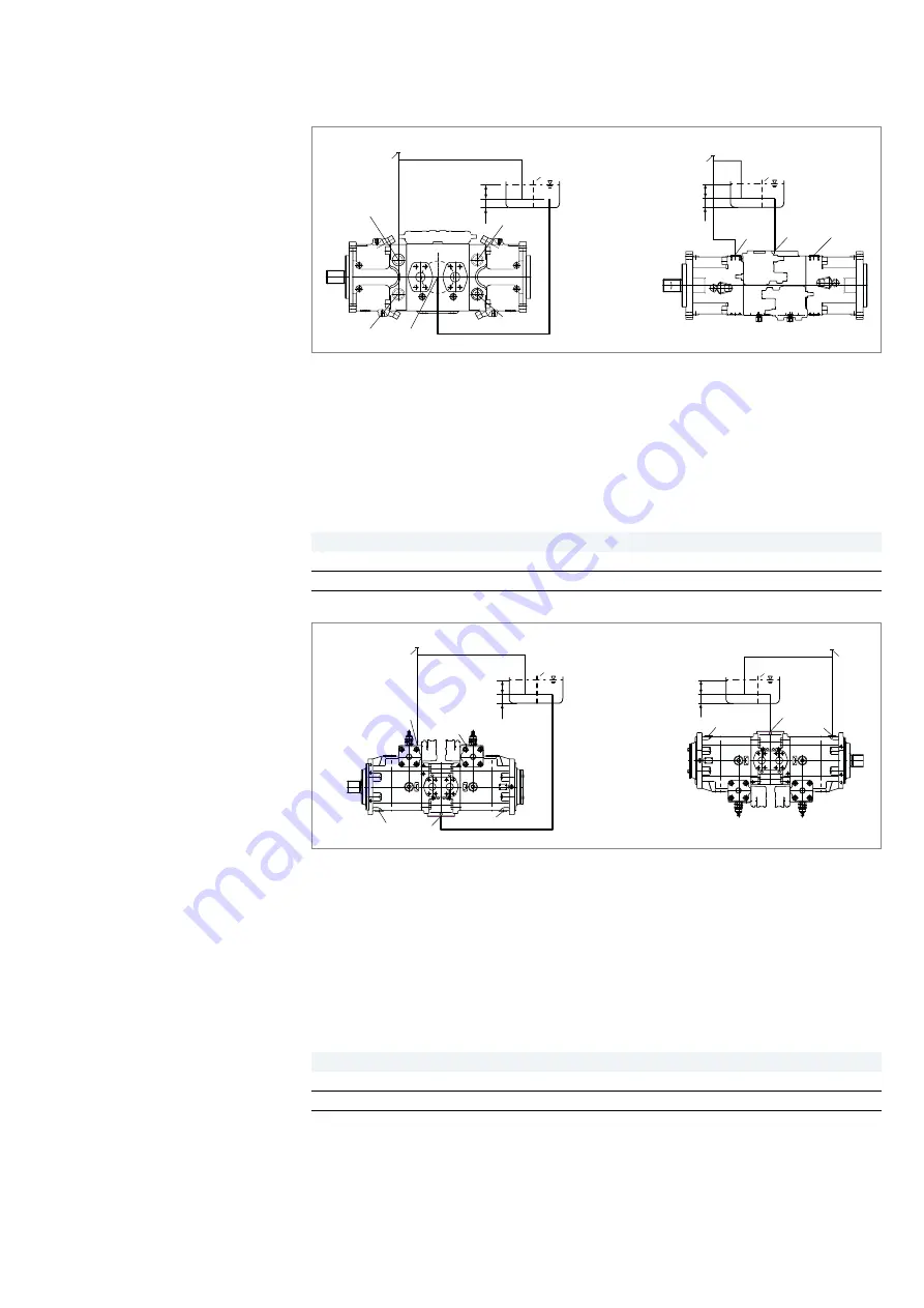
Fig. 10: Below-reservoir installation A20VLO e.g. size 190 with installation position 5–6
F
Filling/air bleeding
h
t min
Minimum required immersion depth
(200 mm)
T
1
,
T
2
Drain port
h
min
Minimum required distance
to reservoir bottom (100 mm)
S
Suction port
SB
Baffle (baffle plate)
Table 9: Below-reservoir installation
Installation position
Air bleed
Filling
5 (drive shaft horizontal)
F
S
+
T
1
6 (drive shaft horizontal)
F
S
+
T
2
7
8
R(L)
2
T
2
T
1
S
SB
h
t min
h
min
F
R(L)
1
S
F
T
2
T
1
SB
h
t min
h
min
Fig. 11: Below-reservoir installation A20VO size 520 with installation position 7–8
F
Filling/air bleeding
h
t min
Minimum required immersion depth
(200 mm)
R(L)
1
,
R(L)
2
Air bleed port
h
min
Minimum required distance
to reservoir bottom (100 mm)
T
1
,
T
2
Drain port
SB
Baffle (baffle plate)
S
Suction port
Table 10: Below-reservoir installation
Installation position
Air bleed
Filling
7 (drive shaft horizontal)
F
S
+
R(L)
1
8 (drive shaft horizontal)
F
S
+
T
1
Below-reservoir
installation A20V(L)O
Sizes 95 to 260
Below-reservoir
installation A20VO
Size 520


