background image

Access Easy Controller 

Hardware Manual

en

Hardware Manual Ver. 2.0.0

Summary of Contents for Access Easy Controller

Page 1: ...Access Easy Controller Hardware Manual en Hardware Manual Ver 2 0 0 ...

Page 2: ...gram to function improperly or not at all BOSCH SECURITY SYSTEMS may not provide support for systems operating under such conditions All efforts have been made to ensure the accuracy of the contents of this manual The above notwithstanding BOSCH SECURITY SYSTEMS assume no responsibility for any errors in this manual or their consequences The information on this document is subject to change withou...

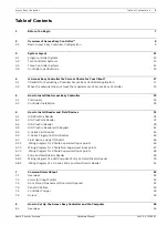
Page 3: ...tion 24 6 How to Install Reader and Field Devices 31 6 1 HID MiniProx Reader 35 6 2 HID ProxPoint Reader 37 6 3 HID ProxPro Reader 39 6 4 HID ProxPro Reader with Keypad 41 6 5 S Series Card Reader 43 6 6 S Series Fingerprint Card Reader 45 6 7 Field devices using I O board 46 6 7 1 Wiring Diagram for 2 State Supervised Input points 46 6 7 2 Wiring Diagram for 2 State Non Supervised Input points 47...

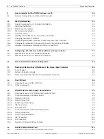
Page 4: ...ser Set up on a Windows Computer 77 11 2 Web Browser Set up on a Macintosh Computer 81 12 How to Set Initial Controller Configuration 84 13 Restoring a Backup Copy of Database to the Access Easy Controller 86 13 1 Tools Needed 86 13 2 Before Starting the Update 86 13 3 Recovering Controller database from a Windows Computer 87 14 The CPU Card 88 14 1 Component Layout of the CPU Card 89 14 1 1 Other...

Page 5: ... of 15VDC Input Power Supply Card 138 19 Convertor Card 141 19 1 Connector Layout of Convertor Card 141 19 1 1 Technical Overview of Convertor Card 143 19 1 2 Jumper Setting 148 19 1 3 LED Indicators 151 20 Power Supply Requirement and Connection 152 20 1 Current Consumption 152 20 2 Connection in the Main Controller 153 20 3 Connection in the Access Easy Extension Unit 158 21 Card Reader Keypad F...

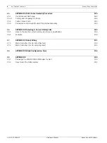
Page 6: ...Procedure to terminate Modular Plug Cable Assembly 186 26 APPENDIX B Selecting A Correct Battery Size 189 26 1 How to choose the correct battery size for your application 189 26 2 Example 190 27 APPENDIX C Detail Wiring 191 27 1 Main Controller for UL Listed System 192 27 2 Main Controller for CE Listed System 194 28 APPENDIX D Blank Configuration Form 196 29 APPENDIX E 199 29 1 Preparing the WAVE...

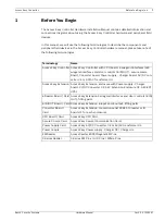
Page 7: ...secure comm Board Converter board Power supply Charger board AC DC con verter CE or AC AC Transformer UL Access Easy Extension Access Easy Extension enclosure with Power supply Charger board DC DC Converter CE AEC Extension Enclosure CE AEC EXT UPS1 4 Reader Board Card Access Easy Extension 4 wiegand interfaces and door controls 8 IN OUT fitting parts 8 IN OUT Board Card Access Easy Extension 8 in...

Page 8: ...olled doors for Door Held and Door Forced conditions X Alarm monitoring of non reader doors and other inputs X Manual door unlocking and locking X Automatic door locking and unlocking based on schedules X Automatic Arming and Disarming of input points X Lighting and output control based on schedules X Special scheduling option for holidays X Built in reporting capabilities X Common alarm output fo...

Page 9: ... 8 Output card provides the circuitry necessary to moni tor 8 alarm type non reader inputs and to control up to eight external devices such as bells fans lights etc The card also provides wiring termination points for the input and output devices The card interfaces to the CPU card via the RS485 Convertor card Power for the card is provide by a separate two wire connection from Power Supply Card P...

Page 10: ...Overview of Access Easy Controller Access Easy Controller Ver 2 0 0 2006 07 Hardware Manual Bosch Security Systems Access Easy Controller is compliance to the following industrial standards X CE X FCC X UL294 ...

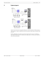
Page 11: ...h Ethernet Card to Access Easy Controller Option II LAN connection Computer with Ethernet Card to network Hub Access Easy Controller to Net work Hub System configurations vary based on capacities required by the customer The following three tables detail Access Easy Controller system configurations and the hardware required to obtain the desired capacity ...

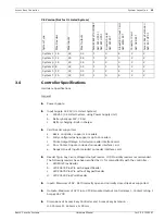
Page 12: ...EC 8W UPS 2 4 reader board AEC 4W EXT 8 Input 8 Output Card AEC 8I8O EXT Converter Card AEC SER EXT Access Easy Extension AEC EXT UPS 2 System A 4 0 0 1 System B 8 0 0 1 1 System E 4 8 8 1 1 System Type Max Readers Max Inputs Max Outputs Access Easy Controller AEC 4W UPS 1 AEC 8W UPS 1 4 reader board AEC 4W EXT 8 Input 8 Output Card AEC 8I8O EXT Converter Card AEC SER EXT Access Easy Extension AEC...

Page 13: ...S 2 AEC 8W UPS 2 4 reader board AEC 4W EXT 8 Input 8 Output Card AEC 8I8O EXT Converter Card AEC SER EXT Access Easy Extension AEC EXT UPS 2 System C 12 0 0 1 2 1 1 System D 16 0 0 1 3 1 1 System F 8 8 8 1 1 1 1 1 System G 12 8 8 1 2 1 1 1 System H 16 8 8 1 3 1 1 1 System I 4 16 16 1 2 1 1 System J 8 16 16 1 1 2 1 1 System K 8 16 16 1 1 2 1 1 System M 8 24 24 1 1 3 1 1 System N 8 24 24 1 1 3 1 1 S...

Page 14: ...6 0 0 1 3 1 1 System F 8 8 8 1 1 1 1 1 System G 12 8 8 1 2 1 1 1 System H 16 8 8 1 3 1 1 1 System I 4 16 16 1 2 1 1 System J 8 16 16 1 1 2 1 1 System K 8 16 16 1 1 2 1 1 System M 8 24 24 1 1 3 1 1 System N 8 24 24 1 1 3 1 1 System Q 4 32 32 1 4 1 1 System Type Max Readers Max Inputs Max Outputs Access Easy Controller AEC 4W UPS 2 AEC 8W UPS 2 4 reader board AEC 4W EXT 8 Input 8 Output Card AEC 8I8...

Page 15: ...D Proximity readers recommended The following readers have been verified by UL for compatibility with the controller a HID MiniProx Reader b HID 20676 ProxPro with Keypad Reader c HID 20676 ProxPro without Keypad Reader d HID 20520 ProxPoint Reader X Inputs Maximum of 32 Both normally open and normally closed devices supported X Outputs Maximum of 32 From C PCB mounted output control relays Contac...

Page 16: ... ply Card 15 VDC from Power Sup ply Card Number of Wiegand Readers Sup ported 4 Number of Input Monitoring Points 8 8 Number of Output Control Relays 8 8 Operating Temperature 0 to 50 deg C Humidity 10 to 95 non condensing Recommended Web Browsers Microsoft Internet Explorer 4 0 and later Netscape Navigator 4 0 and later Netscape 6 0 6 1 and 6 2 are not supported Number of Concurrent Logins 8 Soft...

Page 17: ...can implement to overcome the deficiency and provide the type of network environ ment required by Access Easy Controller If you are unable to answer all items with Yes then Access Easy Controller will not perform reliably for the customer and all alternative access control solution should be considered 4 1 Checklist for Evaluating a Potential Access Easy Controller Application 1 The Access Easy Co...

Page 18: ...t least one computer on the network that is configured for TCP IP _______ Yes _______ No Go to step 2 6 7 The person responsible for managing the Access Easy Controller s database will do so by using a standard Web browser such as Microsoft Internet Explorer or Netscape Naviga tor to communicate with the controller Does this person s computer have an opera tional Web browser on it _______ Yes ____...

Page 19: ... _ _ _ _ _ _ _ _ _ _ _ _ _ _ Outgoing mail server port _ _ _ _ Controller s E mail account name and domain _ _ _ _ _ _ _ _ _ _ _ _ Finally note the following information that will be needed by the installer X Location where the Access Easy Controller is to be installed X Location of the wall jack or hub to be used by the controller to connect to the customer s network 4 2 When the network does not...

Page 20: ...port multiple network adapters Suggest that the customer modify the configuration of one or more computers by adding an Ethernet adapter and configuring Ethernet drivers 2 Dedicate a non networked computer to work with Access Easy Controller This computer will need to be configured with an Ethernet adapter and TCP IP protocol drivers It can then be directly connected to the Access Easy Controller ...

Page 21: ...tocols If the customer s network oper ates using a protocol other than TCP IP then in many cases all that is necessary is to be add the TCP IP protocol into the network environment This type of work should be done by cus tomers their IT department or other computer supplier Possible solutions 1 Modify the existing network configuration to add the TCP IP protocol 2 Provide a non networked computer ...

Page 22: ...erating systems Windows Apple or Unix 2 Dedicate a new computer configured with a browser to work with Access Easy Control ler 2 8 Customer s network can t support static addresses You arrived here because the customer s network configuration is not capable of supporting static IP addresses Many times a customer s network is configured to support Dynamic Address Allocation Under Dynamic Address Al...

Page 23: ... be plugged in to provide the Access Easy Controller with access to the customer s network 2 The customer will also need to provide you with some additional information before the controller can be made operational a An IP address for the controller b The subnet mask to be used by the controller c If a gateway is used by the customer s network then obtain the gateway address to be used by the cont...

Page 24: ... Unit in the Access Easy Controller but do not switch on the power yet X Wire AC power to the strike lock power supply X Pull all required wiring from the controller to field device location 2 Inspect all circuit cards X Check all circuit board mounting screws for snugness X Verify that socket mounted components are secure X Verify jumper and switch settings of all cards 3 Install any needed expan...

Page 25: ...a 12V 7 0AH battery to provide four hours of standby power as required by UL X Use a rubber band or a piece of tape to temporarily close the cabinet tamper switch This should silence the sounder This completes the basic controller installation Refer to the section How to Set Initial con troller Configuration for instructions on setting the controller s IP address RS485 Cable Interconnection for Ac...

Page 26: ...Manual Bosch Security Systems Internal wiring diagram of the AEC for UL Listed System CN2 CN1 T11 J1 T1 1 T1 T2 SECURE COMM CARD 12V7AH BATTERY 18VACINPUTPOWERSUPPLYBOARD T3 2 4 3 5 6 4 3 4 3 2 1 2 1 2 1 4 3 2 1 1 2 3 4 2 1 LAN LAN COM1 VGA PORT2 PORT1 CN11 CPUBOARD CN1 PS2 CHASSI S TAMPER SWI T CH ...

Page 27: ... Ver 2 0 0 2006 07 Internal wiring diagram of the AEC CPU board with USB Port for UL Listed System CN2 CN1 T11 J1 T1 1 T1 T2 SECURE COMM CARD 12V7AH BATTERY 18VACINPUTPOWERSUPPLYBOARD T3 2 4 3 5 6 4 3 4 3 2 1 2 1 2 1 4 3 2 1 1 2 3 4 2 1 LAN LAN COM1 USB VGA PORT1 PS2 PORT2 J5 CPUBOARD CHASSI S TAMPER SWI T CH ...

Page 28: ...en How to Install the Access Easy Controller Access Easy Controller Ver 2 0 0 2006 07 Hardware Manual Bosch Security Systems Internal wiring diagram of the AEC CPU board with USB Port for CE Listed System ...

Page 29: ...he Access Easy Controller en 29 Bosch Security Systems Hardware Manual Ver 2 0 0 2006 07 Internal wiring diagram for Access Easy Extension Unit For UL Listed system 1 F E A C 1 1 2 1 1 2 2 2 4 2 3 1 3 4 2 3 4 2 1 3 4 2 1 3 4 4 3 2 1 6 5 2 1 ...

Page 30: ...ccess Easy Controller Ver 2 0 0 2006 07 Hardware Manual Bosch Security Systems Internal wiring diagram for Access Easy Extension Unit For CE Listed system E F 1 C A L IN ON OFF OUT K J 1 1 2 1 1 2 2 2 4 2 3 1 3 4 2 3 4 2 1 4 3 2 1 4 3 4 2 3 1 6 2 5 1 ...

Page 31: ...box the screws provided with the reader must be used When mounting the reader on any other surface use appropriate fasteners X The shield drain wire from the reader cable should be spliced to the shield conductor of the reader cable coming from the Access Easy Controller The cables shield must be left floating at the controller end This configuration provides the best shielding from exter nal inte...

Page 32: ...asy Controller 8 Input Output card board are designed to handle 1A 24 VDC Resistive If it is necessary to control larger current devices or AC powered devices then external interface relays must be installed 5 Connect all field devices wiring to the 4 reader and 8 Input Output boards in the Access Easy Controller X Refer to the device wiring diagrams in this manual to identify the termination poin...

Page 33: ...er 2 0 0 2006 07 The following readers have been verified by UL for compatibility with the controller X HID MiniProx Reader X HID ProxPro with Keypad Reader X HID ProxPro without Keypad Reader X HID ProxPoint Reader i NOTICE Please refer to chapter 21 for a detail description on the AEC reader Keypad functions ...

Page 34: ...hm ORANGE BELDEN9944 BLACK GREEN WHITE RED BROWN BLACK RED ORANGE WHITE GREEN GreenLED Ground Data 0 Data 1 12 VDC Hold Beeper Red LED BLUE YELLOW HID MINIPROX Pigtail VIOLET Whatisbeingsetup HIDMiniProxReader NormallyOpenExitDevice NormallyClosedDoorContact Fail SaferDCDoorStrike T11 CN1 CN2 T10 1 1 T9 1 T8 1 T7 1 1 T1 T5 JP1 JP2 J2 JP3 J1 T4 1 1 T3 1 1 T2 1 T6 DOORCONTACT 6 8KOhm ...

Page 35: ...he reader Result The green LED should light briefly and the reader should sound a short beep This indicates that the reader recognized the card 3 Depending on the setup of the controller database for the card used in the previous step one of two events will occur within a second of the beep in step 2 Note that either response indicates that the reader is working X If the card is configured to allo...

Page 36: ...TRIKE EXITDEVICE 6 8KOhm ORANGE BELDEN9944 BLACK GREEN WHITE RED BLACK RED ORANGE WHITE GREEN GreenLED Ground Data 0 Data 1 12 VDC HIDPROXPOINT Pigtail Whatisbeingsetup HIDProxPointReader NormallyOpenExitDevice NormallyClosedDoorContact Fail SaferDCDoorStrike T11 CN1 CN2 T10 1 1 T9 1 T8 1 T7 1 1 T1 T5 JP1 JP2 J2 JP3 J1 T4 1 1 T3 1 1 T2 1 T6 DOORCONTACT 6 8KOhm ...

Page 37: ...low access through the reader then the door strike relay on the reader card will activate and the red door strike LED on the same card will light indi cating that access has been granted 3 Depending on the setup of the controller database for the card used in the previous step one of two events will occur within a second of the beep in step 2 Note that either response indicates that the reader is ...

Page 38: ...ata 1 12 VDC Hold Beeper Red LED 8 7 HID PROXPRO Connector Tamper Common 9 Whatisbeingsetup HIDProxProReader NormallyOpenExitDevice NormallyClosedDoorContact Fail SaferDCDoorStrike Tamper Select 10 NoConnection Indicates switch position P1 P2 P3 for Keypadonly P3 1 8 Jumpers andSwitchSetting Ifyou needtoturnthe beeper OFF move SW1 2to OFF position T11 CN1 CN2 T10 1 1 T9 1 T8 1 T7 1 1 T1 T5 JP1 JP2...

Page 39: ...ious step one of two events will occur within a second of the beep in step 2 Note that either response indicates that the reader is working X If the card is configured in the controller s database to allow access through the reader then the LED will light in green for few seconds indicating that access has been granted X Or if the database has not yet been configured then the LED will flash betwee...

Page 40: ...DC Hold Beeper Red LED 8 7 HID PROXPRO with KeyPad Connector Tamper Common 9 Whatisbeingsetup HIDProxProwithKeyPadReader NormallyOpenExitDevice NormallyCloseDoorContact Fail SaferDCDoorStrike Tamper Select 10 NoConnection Indicates switch position P1 P2 P3 for Keypadonly P3 1 8 Jumpers andSwitchSetting Ifyou needtoturnthe beeper OFF move SW1 2to OFF position T11 CN1 CN2 T10 1 1 T9 1 T8 1 T7 1 1 T1...

Page 41: ...ly pressing the numeric keys on the reader s keypad After entering the last digit press the key to complete PIN entry Result An audible beep will be heard after each key is pressed 4 Depending on the setup of the controller database for the card used in the previous step one of two events will occur within a second after pressing the key in the previous step Note that either response indicates tha...

Page 42: ...44 RED WHITE 6 2 1 5 4 3 Data Ret GND Power Gnd Data 0 Data 1 12Vin ALM_LED Green RED STS LED 8 7 S SERIES READER CONNECTION ARM_LED 9 Whatisbeingsetup S SeriesCardReader NormallyOpenExitDevice NormallyClosedDoorContact Fail SaferDCDoorStrike T11 CN1 CN2 T10 1 1 T9 1 T8 1 T7 1 1 T1 T5 JP1 JP2 J2 JP3 J1 T4 1 1 T3 1 1 T2 1 T6 DOORCONTACT 6 8KOhm Buzzer 10 BLUE BLACK ORANGE BLUE Tamper 11 Tamper Com ...

Page 43: ...PIN code by slowly pressing the numeric keys on the reader s keypad After entering the last digit press the Enter key to complete PIN entry Result An audible beep will be heard after each key is pressed 4 Depending on the setup of the controller database for the card used in the previous step one of two events will occur within a second after pressing the Enter key in the previous step Note that e...

Page 44: ...6 2 1 5 4 3 Data Ret GND Power Gnd Data 0 Data 1 12Vin ALM_LED Green RED STS LED 8 7 S SERIES READER CONNECTION ARM_LED 9 Whatisbeingsetup S SeriesCardReader NormallyOpenExitDevice NormallyClosedDoorContact Fail SaferDCDoorStrike T11 CN1 CN2 T10 1 1 T9 1 T8 1 T7 1 1 T1 T5 JP1 JP2 J2 JP3 J1 T4 1 1 T3 1 1 T2 1 T6 DOORCONTACT 6 8KOhm Buzzer 10 BLUE BLACK ORANGE BLUE Tamper 11 Tamper Com 12 BLACK R E ...

Page 45: ...g that the PIN code should be entered Enter the card s PIN code by slowly pressing the numeric keys on the reader s keypad After entering the last digit press the Enter key to complete PIN entry Result An audible beep will be heard after each key is pressed 5 Depending on the setup of the controller database for the card used in the previous step one of two events will occur within a second after ...

Page 46: ...r to have the flexibility of configuring any input in the panel to be in any monitoring requirement The following diagrams shows wiring diagram for 2 State Non Supervised 2 State Supervised and 4 State Supervised input points 6 7 1 Wiring Diagram for 2 State Supervised Input points T1 CN2 1 CN1 T5 T4 1 1 T3 1 1 T8 T7 T2 1 T6 1 JP2 6 8KOhm 6 8KOhm NORMALLYOPEN INPUTPOINT NORMALLYCLOSED INPUTPOINT ...

Page 47: ...w to Install Reader and Field Devices en 47 Bosch Security Systems Hardware Manual Ver 2 0 0 2006 07 6 7 2 Wiring Diagram for 2 State Non Supervised Input points 1 1 1 1 1 1 1 WIRING INPUTS P N AEC 8I8O EXT 8 INPUT OUTPUT CARD ...

Page 48: ...ader and Field Devices Access Easy Controller Ver 2 0 0 2006 07 Hardware Manual Bosch Security Systems 6 7 3 Wiring Diagram for 4 State Supervised Input points 1 1 1 1 1 1 1 WIRING INPUTS P N AEC 8I8O EXT 8 INPUT OUTPUT CARD ...

Page 49: ...ing 5 Click on the I O Settings to configure the I Os of the reader 6 At this point you should configure all the settings related to the door access such as door strike timer door contact door strike etc 7 Choose the output that is wired to the reader buzzer control and save the setting 8 Complete the rest of the setup as per a normal door access reader 9 You need to configure the cardholder to be...

Page 50: ...eyPad Connector Tamper Common 9 Tamper Select 10 P N ADC PCA 22465U CRC CARD TYPE 3 READER 4 D1 4 T11 CN1 CN2 BUZ4 LED4 BUZ1 T10 LED3 1 GND D0 4 12V BUZ3 1 GND D1 3 D0 3 12V LED2 T9 BUZ2 1 GND D0 2 D1 2 12V READER 3 READER 2 T8 1 D0 1 LED1 D1 1 GND 12V T7 IN7 GND IN8GND READER4 READER 1 GND GND IN6 IN5 READER3 1 COM8 15VDC OUT 1 1 15VDC IN 1 N 08 N C8 T1 T5 N 02 JP1 JP2 J2 JP3 J1 T4 N C6 COM7 N C7...

Page 51: ...BUZ4 LED4 BUZ1 T10 LED3 1 GND D0 4 12V BUZ3 1 GND D1 3 D0 3 12V LED2 T9 BUZ2 1 GND D0 2 D1 2 12V READER 3 READER 2 T8 1 D0 1 LED1 D1 1 GND 12V T7 IN7 GND IN8GND READER4 READER 1 GND GND IN6 IN5 READER3 1 COM8 15VDC OUT 1 1 15VDC IN 1 N 08 N C8 T1 T5 N 02 JP1 JP2 J2 JP3 J1 T4 N C6 COM7 N C7 N 06 N 07 1 N 05 COM6 N C5 COM5 1 N C4 N 04 T3 N 03 COM4 N C3 COM3 1 IN1 1 IN3 IN4 GND GND READER2 GND IN2 GN...

Page 52: ...ll remain activated until the condition that caused activation returns to normal In the event multiple alarms exist within the controller the Common Alarm output will remain activated until all alarm conditions have restored A duress condition is an exception to the processing explained in the previous paragraph The Common Alarm output will activate immediately when any user of a card reader signa...

Page 53: ...er supply is restored 7 5 Controller Tamper Whenever the Controller s cover is opened the message Controller Tamper will be sent to the View Activity web page The Common Alarm Output will be triggered on and it is only restored when the Controller s cover is closed back 7 6 Duress Whenever a cardholder activates a duress code the message Duress will be sent to the View Activity web page The Common...

Page 54: ...ccess Easy Controller Ver 2 0 0 2006 07 Hardware Manual Bosch Security Systems 1 1 1 1 1 1 1 1 1 1 1 READER 1 READER 2 READER 4 READER 3 4 READER BOARD P N AEC 4W EXT 2 4 3 COMMON NORMALLY CLOSED NORMALLY OPEN COMMON ALARM OUTPUT ...

Page 55: ...ll be necessary is to configure the computer s network settings so that it has an address on the same network as the controller For initial setup of the Access Easy Controller a Notebook or Desktop computer will be required The computer that will be used for controller setup must have a 10 100Base T Ethernet card installed in it and must run a Window or Macintosh operating system Any ver sion of W...

Page 56: ...econd is for Apple Macintosh Network Configuration on a Windows Computer Windows XP The example described here is based on Window XP Slight differences will be noticed in some dialog boxes displays and descriptions when the computer is configured with a differ ent version of the Windows operating system Even with a different version of Windows the configuration principals are the same the steps ar...

Page 57: ...component is found highlight it by single clicking on it Then skip forward to step 8 of this procedure However if the component is not found continue with steps 4 to 7 and install the compo nent 4 If TCP IP is not found then you will need to install it To add the TCP IP component click on the button to bring up the following dialog box 5 Highlight the Protocol line by single clicking on it and the...

Page 58: ...nent installation Follow any instructions that may be displayed on the screen Note that the system may ask you to insert your Win dows Installation Disk in the CD ROM drive When finished go back to step 3 and select the TCP IP Protocol network adapter line from the list of installed network components Then proceed to step 8 8 With the TCP IP adapter component highlighted click to define the TCP IP...

Page 59: ...ter verifying that the IP address and subnet mask have been correctly entered 12 The computer will proceed to configure the TCP IP settings When it is finished you will be prompted to reboot the computer for the new settings to take effect 9 1 Network Configuration on a Macintosh Computer The example in this section describes the procedure for configuration the network address on an iMac computer ...

Page 60: ...60 en How to Install Set the TCP IP Address on a PC Access Easy Controller Ver 2 0 0 2006 07 Hardware Manual Bosch Security Systems Result The TCP IP dialog box will be displayed as shown following ...

Page 61: ...006 07 3 Enter the IP Address and Subnet Mask Address The example above show the recom mended address and subnet mask to assign to the computer to communicate with a brand new Access Easy Controller as received from the factory 4 Click Save when prompted This message shown below will appear 5 Click Save to confirm the action ...

Page 62: ...orts dial up networking in much the same manner as is used forconnecting to a Internet Ser vice Provider Modem Guidelines The Access Easy Controller software has been designed to be as generic as possible in the implementation of modem support and dial up networking However modems tend to have varying characteristics and attributes from one manufacturer to the next and often from one model to the ...

Page 63: ... confirms continued control ler operation including access control decision marking under fault conditions on the wiring between the controller s serial port and the external modem 10 2 Installing the Modem 1 Connect the modem to the Access Easy Controller s serial port using the cable provided with the modem If this is a UL compliant installation be sure to adhere to the guidelines in the previou...

Page 64: ...ccess Easy Controller Ver 2 0 0 2006 07 Hardware Manual Bosch Security Systems CPU board LAN LAN COM 1 VGA PORT 2 PORT 1 PIN 1 CN11 P N AECMODCPU CPU BOARD PIN 1 CN1 PS2 12VDC 5VDC Connector EnternetLanPort SerialComPortforModem ...

Page 65: ...Networking en 65 Bosch Security Systems Hardware Manual Ver 2 0 0 2006 07 CPU board with USB Port 12VDC 5VDC Connector EnternetLanPort SerialComPortforModem LAN LAN PIN 1 COM 1 USB VGA PORT1 PS2 PORT2 J5 CPU BOARD P N AECMODCPU PIN1 ...

Page 66: ... Modem Switch Settings Switch Setting Function 1 OFF Data Terminal Ready DTR Override X OFF Normal DTR operations computer must provide DTR signal for the modem to accept comment dropping DTR ter minates a call X ON Modem ignores DTR Override 2 OFF Verbal Numeric Result Codes X OFF Verbal word results X ON Numeric results 3 ON Result Code Display X OFF Suppresses result codes X ON Enables result c...

Page 67: ...structs the modem to save the current setup The commands sent to the modem by the controller are listed below attTone mode atzReset ate0Echo Off ats0 1One ring to autoanswer atb0Selects the ITU T V 25 answer sequence at b1Fixed DTE speed serial port rate at wSave settings 8 Test the modem and modem to controller wiring by dialling the phone number to which the modem is connected from any standard ...

Page 68: ...are used only with dial up networking is user configurable Second there is a parameter that specifies the maximum number of unsuccessful login attempts that will be allowed When this value is reached without a successful dial up login having occurred the controller will automatically disable the dial in capability for a user spec ified period of time The default settings for the security features ...

Page 69: ... line The following describes the necessary procedures to configure dial up network ing 1 Log into Access Easy Controller and select Panel Admin The following is displayed 2 Select Dial in User to display the following 3 The default Dial in user name is PPP and the default password is 8088 For security purposes we suggest you change the default User Name and Password 4 Adjust the Dial in setting a...

Page 70: ...ed automatically by Access Easy Controller based on the network address that is assigned to the controller during the installation and setup pro cess If the controller is assigned a Class A network address then the controller will automat ically configure the dial in IP address to a Class C address If the controller is assigned a Class B or Class C network address then dial up networking will auto...

Page 71: ...he computer that will be dialling into the Access Easy Controller II select Start Pro grams Accessories Communications Dial Up Networking Result The following window is displayed 2 Double click Make New Connection and the following window is displayed Enter a name for the connection eg Access Easy Controller HQ 3 Follow all on screen instructions Make sure a modem is connected to your computer Sel...

Page 72: ...ting the General tab and setting available option as appropriate Select the communications port and accept the maximum speed default setting 6 After configuring your modem click OK and continue with the Make New Connection dia log box as shown on the following page Enter the controller s area code and phone num ber Select your country or region code ...

Page 73: ...ardware Manual Ver 2 0 0 2006 07 7 Enter the telephone number for the Access Easy Controller to which you want to connect click Next and follow the following window is displayed 8 Click Finish 9 Return to Dial in Networking as explained in step 1 to view your new connection ...

Page 74: ...er the IP address of the Access Easy Controller in the address or location bar of the browser and press ENTER If you have successfully connected to the controller the Access Easy Controller Login screen is displayed 13 Log in to the controller by entering a valid User ID and password and click Login i NOTICE Please be patient It will take about 30 seconds from the time the controller s modem answe...

Page 75: ...Config ure to Using PPP Server 3 Next select Remote Access from the Control Panel sub menu 4 The Remote Access dialog box is displayed Enter the dial in user name and password for the Access Easy Controller to which you want to connect Also enter the dial in number in the Number field 5 Click Connect to remotely access the Access Easy Controller i NOTICE Point to Point Protocol is a protocol for c...

Page 76: ...ase where a user may attempt to connect to Access Easy Controller over a dial up connection from a computer that is on the same local area network as the controller there is a possibility that Internet Explorer may not be able to establish the dial up connection with the controller There is a setting on the computer that can be changed to force the browser to use the dial up connection In the Wind...

Page 77: ...nect to an Access Easy Controller The guide lines presented in this section are intended for first time browser users and as a technical ref erence if difficulty is encountered when connecting with an Access Easy Controller 11 1 Web Browser Set up on a Windows Computer Follow this procedure to configure Microsoft s Internet Explorer version 6 0 Other Web browsers will be similar 1 From the Windows...

Page 78: ...ns of stored pages is set to Automatically as shown If it is not select the corresponding radio button to select this option This step is necessary for the View Activity windows to refresh properly at regular intervals 4 Click to save the changes and exit the Settings windows You will return to the Internet Option dialog box shown on the previous page 5 From the Internet Option screen select the C...

Page 79: ...n the Exceptions field sepa rating each address with a semicolon Note that there may already be addresses listed in the exception field If that is the case simply add the Access Easy Controller address to the list separating each address with a semicolon The screen capture below shows the default IP Address for Access Easy Controller along with three other IP Addresses 129 3 0 202 129 3 0 203 and ...

Page 80: ...assword 8088 Upon successful login the controller s home page will be displayed 15 From the home page select Panel Admin Panel Setup The Network Settings page should be displayed Make any needed changes to configure the controller for operation on the customer s network Click Save to store the changes 16 After the database has been saved reboot the controller It will now boot using the new IP addr...

Page 81: ...h Internet Explorer for Macintosh 2 From the Toolbar click Preferences 3 Under the Web Browser select Advanced The Advanced Settings screen will be dis played as following 4 In the Cache group box set the Update pages option to Always by selecting the radio but ton 5 If your network does not use a proxy server then you can skip directly to step 8 if your network does use a proxy server then scroll...

Page 82: ...at there may already be IP addresses listed in this box If that is the case simply add the Access Easy Controller address to the list separating each address with a space or comma The sample box shown at the top of the next page shows the default IP Address for Access Easy Controller along with three other IP Addresses 129 2 0 45 129 2 0 44 and 129 3 0 80 9 Click OK to close the dialog box 10 Make...

Page 83: ... 8088 Upon successful login the controller s shown page will be displayed 14 From the home page select the Panel Admin Panel Setup The Network Settings page should be displayed Make any needed changes to configure the controller for operation on the customer s network Click Save to store the changes 15 After the database has been saved reboot the controller It will now boot using the new IP addres...

Page 84: ...nately flash in the lower corner of the Secure Communication Card X Wait until the self test is complete before proceeding 3 On the computer open a Web browser application either Microsoft Internet Explorer or Netscape Navigator and enter the controller s IP address 129 2 0 41 in the browser s address or location bar Then click GO or press ENTER to connect to the controller X If you have never use...

Page 85: ...to test it using the new settings to confirm proper setup X To do this you will need to change the network configuration of your computer to an address on the same network as the controller X As an example assume that in the previous steps you set the controller s address to 192 9 200 18 and the Subnet mask to 255 255 0 0 To test the controller using your com puter the computer s network setup wil...

Page 86: ... Connectivity between the computer containing the database and the controller through the network or directly by use of a crossover cable 13 2 Before Starting the Update 1 Be sure the controller is currently operating by logging on the controller or having the customer log on to the controller 2 While logged on select Panel Admin Panel Setup and note the IP addresses and PC names listed under the ...

Page 87: ...o select the file you wish to upload example if you are uploading the backup system database select the db_tar gz from your local directory 3 Click on button to upload 4 Once the file appears in the List of Uploaded Files you could now click on the icon to start the updating process The following dialog box will appear for confirmation 5 Click on the OK button to proceed Once the process is comple...

Page 88: ...on Card which provides the security and the RS485 conversion It is designed to function as both an embedded Web server and an Access Control Controller Two communication ports are available on the CPU card The first is an 100Base T Ethernet port that is used by the Web server for communication with the customer s monitoring and database management computers The Ethernet port terminates in an RJ 45...

Page 89: ... on the CPU Card A brief description is provided on some of the major components We have 2 different types for the CPU Card hence the layout of each type will be slightly dif ferent The following drawings will show each type and the location of the relevant compo nents CPU board LAN LAN COM 1 VGA PORT 2 PORT 1 PIN1 CN11 P N AECMODCPU CPU BOARD PIN1 CN1 PS2 12VDC 5VDC Connector EnternetLanPort Seri...

Page 90: ... Port Specification for CPU Input Voltage 5VDC 4 75V to 5 25V Current Consumption 1 35A 5VDC Peak 1 25 A 5VDC Idle Interface 1 x Serial Port Parallel Port 10 100BaseT Fast Ethernet 12VDC 5VDC Connector EnternetLan Port Serial ComPortforModem LAN LAN PIN 1 COM 1 USB VGA PORT1 PS2 PORT2 J5 CPU BOARD P N AEC MODCPU PIN1 ...

Page 91: ...ail Serial Port Parallel Port Connector for Secure Communication Card These are 9pin serial port and 25pin parallel port connectors These are the links between CPU Card and Secure Communication Card The serial port is connected to the Secure Com munication Card CN2 parallel port is connected to CN1 of Secure Communication Card 100Base Tx Ethernet connector 1 Tx 2 Tx 3 Rx 4 NC 5 NC 6 Rx 7 NC 8 NC P...

Page 92: ...um battery is situated It is used to provide continuous supply to the Real Time Clock circuitry in case of a power outage The power will only be drawn from this battery on the following conditions 1 No power is present to either one of the supply terminal blocks 18VAC IN or 15VDC IN and 2 The external 12V rechargeable battery is not charged sufficiently or is drained for prolong period of time and...

Page 93: ...rdware There is also an 8 Input 8 Output board available which provides eight zones of end of line resistor type inputs and eight contact closure outputs This board is intended for non reader type applications where it is desirable to monitor such things as emergency exit doors or motion detectors This card also provides eight form C type relay outputs which can be used to control external equipme...

Page 94: ... STRIKE OUTPUT READER2 STRIKE OUTPUT COMMON NORMALLYCLOSED NORMALLYOPEN NORMALLYOPEN NORMALLYCLOSED COMMON READER4 OUTPUT STRIKE READER3 STRIKE OUTPUT COMMON NORMALLYCLOSED NORMALLYOPEN NORMALLYOPEN NORMALLYCLOSED COMMON COMMON NORMALLYCLOSED NORMALLYOPEN NORMALLYOPEN NORMALLYCLOSED COMMON SPARE SPARE OUTPUT STRIKE STRIKE OUTPUT SPARE OUTPUT STRIKE SPARE STRIKE OUTPUT CONTACT REX CONTACT REX CONTA...

Page 95: ...T 1 COMMON NORMALLY CLOSED NORMALLY OPEN NORMALLY OPEN NORMALLY CLOSED COMMON COMMON NORMALLY CLOSED NORMALLY OPEN NORMALLY OPEN NORMALLY CLOSED COMMON COMMON NORMALLY CLOSED NORMALLY OPEN NORMALLY OPEN NORMALLY CLOSED COMMON INPUT 1 GROUND OUT 15VDC OUT RELAY OUTPUT 2 RELAY OUTPUT 3 RELAY OUTPUT 4 RELAY OUTPUT 5 RELAY OUTPUT 6 RELAY OUTPUT 7 RELAY OUTPUT 8 INPUT 2 INPUT 3 INPUT 4 INPUT 5 INPUT 6 ...

Page 96: ...rol there are two terminals each for connection of a door contact and a request to exit device Both circuits contact and REX are supervised and should be terminated with 6 8K end of line resistors Should either contact or REX device not be used then the termination resistor should be installed across the terminals within the controller Refer to the Chapter How to Install Readers and Field Devices ...

Page 97: ... Reader board On 4 reader board 1 the last relay is assigned in the software to provide a common alarm out put from the controller This relay is intended to provide an easy hand off by the controller of an alarm indication to an external burglar alarm system The common alarm relay will activate whenever a Door Forced Open or Door Held Open alarm is detected by the controller It will also activate ...

Page 98: ...osed 3 Reader 3 normally open 4 Reader 4 common 5 Reader 4 normally closed 6 Reader 4 normally open Connector T4 third connector from top Pin Function 1 Spare common 2 Spare Normally closed 3 Spare normally open 4 Spare common 5 Spare normally closed 6 Spare normally open Connector T5 bottom connector Pin Function 1 Spare common 2 Spare Normally closed 3 Spare normally open 4 Common Alarm Output c...

Page 99: ... pin IDE connectors They are used as the data link between the 4 reader board and other 4 reader board and or 8input 8output card board The connector is used to extend the IDE bus to the next card 15 2 5 LED Indicators Reference LED9 This LED indicates 15 VDC power is present Reference LED 1 to LED 8 LEDs 1 to 8 light whenever the associated relay is activated Reference LED 11 and LED 13 These LED...

Page 100: ...r the third and fourth readers Reference JP1 Jumper JP1 sets the addresses for the door contacts request to exit inputs and door strike outputs Reference J1 and J2 These jumpers are not in used in the Access Easy Controller application They are reserved for future implementation 4 reader board Address JP1 JP2 JP3 1 1 2 OUT 1 2 OUT 1 2 IN 3 4 OUT 3 4 OUT 3 4 OUT 5 6 OUT 5 6 OUT 5 6 OUT 2 1 2 IN 1 2...

Page 101: ...d should be termi nated with 6 8K end on line resistors All unused should have the termination resistor installed across the terminals within the controller Refer to the Chapter entitled How to Install Readers and Field Devices for detailed wiring diagrams The charts that follow identify the various termination points on the terminal strips T6 terminal Strip INO1 Input Point 1 GND Input Point 1 IN...

Page 102: ...ith AC power devices In all instances where the output relay is used to operate an inductive load such as when interfacing with an external relay or powering the coil of an alarm bell a back biased diode should be wired across the coil of the driven device This will protect the electronic circuitry on the 8 Input Output card board by providing suppression from back emf when the devices are de acti...

Page 103: ... open 4 Output 4 common 5 Output 4 normally closed 6 Output 4 normally open Connector T4 third connector from top Pin Function 1 Output 5 common 2 Output 5 normally closed 3 Output 5 normally open 4 Output 6 common 5 Output 6 normally closed 6 Output 6 normally open Connector T5 bottom connector Pin Function 1 Output 7 common 2 Output 7 normally closed 3 Output 7 normally open 4 Output 8 common 5 ...

Page 104: ...1 1 and T1 2 of the next interface card The diagram below shows the configuration of terminal strip T1 Refer to the Chapter entitle The CPU Card for additional details 15 3 3 IDE Connectors Reference CN1 and CN2 These are a pair of parallel connected 40 pin IDE connectors They are used as the data link between the 8 Input Output card board and other 4 reader board and or 8 Input Output card board ...

Page 105: ...used to set the card address as shown following 15 4 Reader I O Board Address Settings The following diagrams shows the detailed drawing digram of 4 Reader Board and 8 Input Output Board and their jumper settings for each card 8 Input Output card board Address JP1 1 1 2 OUT 3 4 OUT 5 6 OUT 2 1 2 IN 3 4 OUT 5 6 OUT 3 1 2 OUT 3 4 IN 5 6 OUT 4 1 2 IN 3 4 IN 5 6 OUT ...

Page 106: ...1 STRIKE OUTPUT READER2 STRIKE OUTPUT COMMON NORMALLYCLOSED NORMALLYOPEN NORMALLYOPEN NORMALLYCLOSED COMMON READER4 OUTPUT STRIKE READER3 STRIKE OUTPUT COMMON NORMALLYCLOSED NORMALLYOPEN NORMALLYOPEN NORMALLYCLOSED COMMON COMMON NORMALLYCLOSED NORMALLYOPEN NORMALLYOPEN NORMALLYCLOSED COMMON SPARE SPARE OUTPUT STRIKE STRIKE OUTPUT SPARE OUTPUT STRIKE SPARE STRIKE OUTPUT CONTACT REX CONTACT REX CONT...

Page 107: ...5 STRIKE OUTPUT READER6 STRIKE OUTPUT COMMON NORMALLYCLOSED NORMALLYOPEN NORMALLYOPEN NORMALLYCLOSED COMMON READER8 OUTPUT STRIKE READER7 STRIKE OUTPUT COMMON NORMALLYCLOSED NORMALLYOPEN NORMALLYOPEN NORMALLYCLOSED COMMON COMMON NORMALLYCLOSED NORMALLYOPEN NORMALLYOPEN NORMALLYCLOSED COMMON SPARE SPARE OUTPUT STRIKE STRIKE OUTPUT SPARE OUTPUT STRIKE SPARE STRIKE OUTPUT CONTACT REX CONTACT REX CONT...

Page 108: ...E OUTPUT READER 10 STRIKE OUTPUT COMMON NORMALLY CLOSED NORMALLY OPEN NORMALLY OPEN NORMALLY CLOSED COMMON READER 12 OUTPUT STRIKE READER 11 STRIKE OUTPUT COMMON NORMALLY CLOSED NORMALLY OPEN NORMALLY OPEN NORMALLY CLOSED COMMON COMMON NORMALLY CLOSED NORMALLY OPEN NORMALLY OPEN NORMALLY CLOSED COMMON SPARE SPARE OUTPUT STRIKE STRIKE OUTPUT SPARE OUTPUT STRIKE SPARE STRIKE OUTPUT CONTACT REX CONTA...

Page 109: ...LY OPEN NORMALLY CLOSED COMMON SPARE SPARE OUTPUT STRIKE STRIKE OUTPUT SPARE OUTPUT STRIKE SPARE STRIKE OUTPUT 12 VDC RED GROUND BLACK DATA 0 GREEN DATA 1 WHITE LED ORANGE NO CONNECTION NO CONNECTION LED ORANGE DATA 1 WHITE DATA 0 GREEN GROUND BLACK 12 VDC RED NO CONNECTION LED ORANGE DATA 1 WHITE DATA 0 GREEN GROUND BLACK 12 VDC RED NO CONNECTION LED ORANGE DATA 1 WHITE DATA 0 GREEN GROUND BLACK ...

Page 110: ...T 1 COMMON NORMALLY CLOSED NORMALLY OPEN NORMALLY OPEN NORMALLY CLOSED COMMON COMMON NORMALLY CLOSED NORMALLY OPEN NORMALLY OPEN NORMALLY CLOSED COMMON COMMON NORMALLY CLOSED NORMALLY OPEN NORMALLY OPEN NORMALLY CLOSED COMMON INPUT 1 GROUND OUT 15 VDC OUT RELAY OUTPUT 2 RELAY OUTPUT 3 RELAY OUTPUT 4 RELAY OUTPUT 5 RELAY OUTPUT 6 RELAY OUTPUT 7 RELAY OUTPUT 8 INPUT 2 INPUT 3 INPUT 4 INPUT 5 INPUT 6...

Page 111: ...MON NORMALLY CLOSED NORMALLY OPEN NORMALLY OPEN NORMALLY CLOSED COMMON COMMON NORMALLY CLOSED NORMALLY OPEN NORMALLY OPEN NORMALLY CLOSED COMMON COMMON NORMALLY CLOSED NORMALLY OPEN NORMALLY OPEN NORMALLY CLOSED COMMON INPUT 9 GROUND OUT 15 VDC OUT RELAY OUTPUT 10 RELAY OUTPUT 11 RELAY OUTPUT 12 RELAY OUTPUT 13 RELAY OUTPUT 14 RELAY OUTPUT 15 RELAY OUTPUT 16 INPUT 10 INPUT 11 INPUT 12 INPUT 13 INP...

Page 112: ...MON NORMALLY CLOSED NORMALLY OPEN NORMALLY OPEN NORMALLY CLOSED COMMON COMMON NORMALLY CLOSED NORMALLY OPEN NORMALLY OPEN NORMALLY CLOSED COMMON COMMON NORMALLY CLOSED NORMALLY OPEN NORMALLY OPEN NORMALLY CLOSED COMMON INPUT 17 GROUND OUT 15 VDC OUT RELAY OUTPUT 18 RELAY OUTPUT 19 RELAY OUTPUT 20 RELAY OUTPUT 21 RELAY OUTPUT 22 RELAY OUTPUT 23 RELAY OUTPUT 24 INPUT 18 INPUT 19 INPUT 20 INPUT 21 IN...

Page 113: ...MON NORMALLY CLOSED NORMALLY OPEN NORMALLY OPEN NORMALLY CLOSED COMMON COMMON NORMALLY CLOSED NORMALLY OPEN NORMALLY OPEN NORMALLY CLOSED COMMON COMMON NORMALLY CLOSED NORMALLY OPEN NORMALLY OPEN NORMALLY CLOSED COMMON INPUT 25 GROUND OUT 15 VDC OUT RELAY OUTPUT 26 RELAY OUTPUT 27 RELAY OUTPUT 28 RELAY OUTPUT 29 RELAY OUTPUT 30 RELAY OUTPUT 31 RELAY OUTPUT 32 INPUT 26 INPUT 27 INPUT 28 INPUT 29 IN...

Page 114: ...e Access Easy Controller will not be able to function The second function of the card is to provide communication between the CPU and the Reader boards and I O cards via the Convertor cards It has a RS485 port that will communi cate with the Convertor Cards at 9600bps 16 1 Connector Layout of Secure Communication Card The following layout drawing shows the physical connectors on the Secure Communi...

Page 115: ...Security Systems Hardware Manual Ver 2 0 0 2006 07 Internal wiring diagram between CPU board and Secure Com Card CN2 CN1 B PIN1 PIN1 P N AEC MOD COM SECURE COMM CARD 4 3 2 1 1 2 3 4 2 1 LAN LAN COM 1 VGA PORT 2 PORT 1 PIN1 CN11 P N AECMODCPU CPUBOARD PIN1 CN1 PS2 ...

Page 116: ...th USB port and Secure Com Card CN2 CN1 B PIN1 PIN1 P N AEC MOD COM SECURE COMM CARD 4 3 2 1 1 2 3 4 2 1 LAN LAN PIN 1 COM1 USB VGA PORT1 PS2 PORT2 J5 CPU BOARD P N AEC MOD CPU PIN1 Specification for Secure Communication Card Input Voltage 5VDC 4 75V to 5 25V Current Consumption 36 5mA 5VDC Peak 20 3mA 5VDC Idle Interface Serial Port Parallel Port RS485 Por ...

Page 117: ...e communication link between the CPU and the Secure Communication Card The communication cable is a 9 way ribbon cable with one end a DB9 male connector and the other is a 10pin IDC connector Reference Mains Power Fail T2 1 T2 2 This input allows you to monitor the power source status When there is a power failure from the source it could trigger the common alarm output and register as a controlle...

Page 118: ...dware Manual Bosch Security Systems Internal wiring diagram between Power Supply board UL Listed System and Secure Com Card CN2 CN1 B PIN 1 PIN 1 P N AEC MOD COM SECURE COMM CARD 4 3 2 1 1 2 3 4 2 1 IN T1 T2 P N AECMODUPS2 18VAC INPUT POWER SUPPLYBOARD T3 5 6 4 3 4 3 2 1 2 1 2 1 ...

Page 119: ...ntroller you could uses output provided by the 15V DC Input Power Supply Card to provide the triggering as shown on the following page Internal wiring diagram between Power Supply board CE Listed System and Secure Com Card CN2 CN1 B PIN 1 PIN 1 P N AEC MOD COM SECURE COMM CARD 4 3 2 1 1 2 3 4 2 1 IN T1 T2 T3 P N AECMODUPS1 15VDC INPUT POWER SUPPLY BOARD 4 3 2 1 3 4 2 1 2 1 6 5 ...

Page 120: ...d and the Common Alarm Output CAO relay to trigger on A Controller Tamper alarm message will be sent to the View Activity page Reference DC 15V IN T1 1 T1 2 These 2 terminals are for connection to an external 5VDC source Please read the Chapter on Power Supply Requirement for further information before connecting any power source Reference RS485 connector T3 These terminals are for connection to t...

Page 121: ...g LED 3 Indicates serial communication process is running LED 7 Indicates total communication failure for all extension boards LED 8 Indicates the ARP enabled for IP configuration IP has been reset to default address LED 9 Indicates the CPU is accessing the SAM chip on board the Secure Communication Card Each time the CPU access the SAM this LED will blink once LED 10 11 These two LED indicates th...

Page 122: ...VAC input and provide both the required DC power supply for all the other Cards and attached Readers It is only available on the Main Controller Unit which house the CPU Secure Communication Reader Board and I O Cards The Access Easy Extension unit utilized another simplified Power Supply Card which we will describe in the last section of this chapter i NOTICE This card is only available for UL Li...

Page 123: ... Unit The following layout drawing shows the physical connectors on the 18V AC Input Power Sup ply Card In addition a brief description is provided on some of the major connectors Specification for 18 V AC Input Power Supply Card for Main Controller Unit Input Voltage 18V AC Output Voltage 15V DC 12V DC 5V DC Max Output Current 1A 15V DC 2A 5V DC or 750mA 12V DC 2A 5V DC ...

Page 124: ...2VDC and 5VDC output Reference Main Power Fail Output T2 6 T2 5 This output allows you to indicate the power source status When there is a power failure from the 18VAC it will trigger the Main Power Fail Output from normally close contact to open To utilize this feature you connect this output to the Secure Communication Card s Mains Power Fail input as shown in the following page i NOTICE This ca...

Page 125: ...rest of the cards in the same enclosure Those cards that required the 15VDC are Reader Board I O Cards and the Convertor Card although it is not a must to tap the power form this output it serve as a termination point to loop the power point to the rest of the cards that requires the 15VDC as shown in the following page CN2 CN1 B PIN 1 PIN 1 P N AECMODCOM SECURE COMM CARD 4 3 2 1 1 2 3 4 2 1 IN T1...

Page 126: ...ARD P N AECSEREXT CONVERTERBOARD 4READERBOARD P N AEC4WEXT 12V7AH BATTERY P N AECMODUPS2 18VACINPUTPOWERSUPPLYBOARD T3 2 4 3 5 6 4 3 4 3 2 1 2 1 2 1 4 3 2 1 1 2 3 4 2 1 LAN LAN COM1 VGA PORT2 PORT1 PIN1 CN11 P N AECMODCPU CPUBOARD PIN1 CN1 PS2 CHASSI S TAMPER SWI T CH i NOTICE This output could only provide a Max Output of 15VDC at 1A DO NOT CONNECT ANY HIGH POWER CONSUMPTION DEVICES TO IT All oth...

Page 127: ...dware Reference DC 12V Output DC 5V Output T3 4 T3 3 T3 2 T3 1 These 2 terminal blocks outputs a voltage supply of 12VDC and 5VDC see NOTICE It sup plies power supply to CPU Card within the same enclosure 17 2 18VAC Power Supply Card for Access Easy Extension Unit This is a simplified version of the 18V AC Input Power Supply Card for the Main Controller Unit that was mention in the above It utiliz...

Page 128: ...des a brief description of the uses for each of them Reference AC Input T1 1 T1 2 The 18V AC Input Power Supply Card is designed for UL Listed System only it accepts 18VAC direct on terminal block T1 This card will convert the AC input into 15VDC required by the Reader Board I O and Convertor Card Specification for 18V AC Input Power Supply Card for Access Easy Extension Unit Input Voltage 18V AC ...

Page 129: ...output allows you to indicate the power source status When there is a power failure from the 18VAC input source it will trigger the Main Power Fail Output from normally close contact to open To utilize this feature you need to connect this output to the Converter Card s Mains Power Fail input as shown below T1 18VACINPUTPOWERSUPPLYBOARD T2 CN2 J1 T11 CN1 T1 1 2 3 4 ...

Page 130: ...oard I O Cards and the Convertor Card although it is not a must to tap the power from this output it serve as a termination point to loop the power point to the rest of the cards that requires the 15VDC as shown below i NOTICE This output could only provide a Max output of 15VDC at 1A DO NOT CONNECT ANY HIGH POWER CONSUMPTION DEVICES TO IT All other devices such as Locks should be supplied by a se...

Page 131: ...als are for connection to an external 12V rechargeable battery The battery is trickle charged when ac mains input power is present During a power outage this battery is used to power the card Convertor Cards and the Reader Board and or I O Cards within the same enclosure for a limited duration depending on the total current consumption of the sys tem hardware ...

Page 132: ...U Secure Communication Reader Board and or I O Cards The Access Easy Extension unit utilized another simplified Power Supply Card which we will describe in the last section of this chapter This module is not to be use with UL Listed System 18 1 15V DC Input Power Supply Card for Main Controller Unit The following layout drawing shows the physical connectors on the 15V DC Input Power Sup ply Card I...

Page 133: ...ccepts 15VDC direct on terminal block T1 from an external Power Supply Unit Reference Main Power Fail Output T2 6 T2 5 This output allows you to indicate the power source status When there is a power failure from the 15VDC it will trigger the Main Power Fail Output from normally close contact to open To utilize this feature you need to connect this output to the Secure Communication Card s Mains P...

Page 134: ...Reference DC 15V Output T2 4 T2 3 This output provides the power for the rest of the cards in the same enclosure Those cards that required the 15VDC are CPU Card Reader Board I O Cards and the Convertor Card although it is not compulsory to tap the power from this output it serve as a termination point to loop the power point to the rest of the cards that requires the 15VDC as shown in the fol low...

Page 135: ...ng diagram of AEC CE Listed System 1 C F E A D J K L 1 1 2 1 1 2 2 2 4 2 3 1 3 4 2 3 4 4 3 2 1 3 4 2 1 2 1 6 5 3 1 2 4 4 3 1 2 1 2 i NOTICE This output could only provide a Max output of 15VDC at 1A DO NOT CONNECT ANY HIGH POWER CONSUMPTION DEVICES TO IT All other devices such as Locks should be supplied by a separate power source ...

Page 136: ... battery is used to power the card Convertor Card and the Reader Board and or I O Cards within the same enclosure for a limited duration depending on the total current consumption of the sys tem hardware Reference DC 12V Output DC 5V Output T3 4 T3 3 T3 2 T3 1 These 2 terminal blocks outputs a voltage supply of 12VDC and 5VDC see NOTICE It is use for supplying power to the CPU Card within the same...

Page 137: ... mention in the above It utilized the same card but does not provide any 5VDC and 12VDC This module is not to be use for UL Listed system The following shows the layout of the 15V DC Input Power Supply Card used for Access Easy Extension unit Specification for 15V DC Input Power Supply Card for Access Easy Extension Unit Input Voltage 15V DC Output Voltage 15V DC 12V DC 5V DC Max Output Current 1A...

Page 138: ... the world that does not requires UL Listing it accepts 15VDC direct on terminal block T1 This card will supplies the 15VDC required by the Reader Board I O and Convertor Card Reference Main Power Fail Output T2 6 T2 5 This output allows you to indicate the power source status When there is a power failure from the 15VDC input source it will trigger the Main Power Fail Output from normally close c...

Page 139: ...or the rest of the cards in the same enclosure Those cards that required the 15VDC are Reader Board I O Cards and the Convertor Card although it is not a must to tap the power from this output it serve as a termination point to loop the power point to the rest of the cards that requires the 15VDC as shown in the following dia gram CN2 J1 T11 CN1 T1 1 15VDCINPUTPOWERSUPPLYBOARD T2 T1 2 3 4 ...

Page 140: ...s present During a power outage this battery is used to power the card and the Reader Board and or I O Cards within the same enclosure for a limited duration depending on the total current consumption of the system hardware T11 CN1 CN2 1 T1 J1 15VDCINPUTPOWERSUPPLYBOARD T2 T1 2 3 4 i NOTICE This output could only provide a Max output of 15VDC at 1A DO NOT CONNECT ANY HIGH POWER CONSUMPTION DEVICES...

Page 141: ...t to be mounted separately away from the Main Controller Unit With the use of RS485 communication the Access Easy Extension unit can be mounted as far as 1Km away from the Main Controller and multiple Access Easy Extension units could be linked via this RS485 communication link by daisy chain as shown in the diagram below 19 1 Connector Layout of Convertor Card i NOTICE Maximum distance between Ma...

Page 142: ... 2006 07 Hardware Manual Bosch Security Systems The following layout drawing shows the physical connectors on the Convertor Card J1 JP1 JP3 JP2 Specification for Convertor Card Input Voltage 15V DC Current Consumption 26 6mA 15V DC Peak 25mA 15V DC Average ...

Page 143: ...s of the Access Easy Extension unit When there is a power failure from the source it could trigger the common alarm output and register as a controller AC fail in the View Activity To utilize this feature you will need to ter minate this to the Power Supply Card s MAINS PWR FAIL OUT The UL Listed version of Access Easy Controller uses the 18V DC input power supply card that provides a Mains Power ...

Page 144: ...144 en Convertor Card Access Easy Controller Ver 2 0 0 2006 07 Hardware Manual Bosch Security Systems T1 18VACINPUTPOWERSUPPLYBOARD T2 CN2 J1 T11 CN1 T1 1 T3 2 3 4 ...

Page 145: ...ual Ver 2 0 0 2006 07 If you are having the CE Listed version of Access Easy Controller you could use the output provided by the 15V DC Input Power Supply Card to provides the triggering as shown in the following diagram CN2 J1 T11 CN1 T1 1 15VDCINPUTPOWERSUPPLYBOARD T2 T1 T3 2 3 4 ...

Page 146: ... Panel Tamper alarm message will be sent to the View Activity page Reference RS485 IN T1 and RS485 OUT T2 These terminals are for the daisy chain connection of the RS485 communication between the Secure Communications and the Converter Cards Each IN should be connected to the previ ous OUT in the daisy chain loop The following diagram shows how the Converter Cards and the Secure Communication Card...

Page 147: ...Access Easy Controller Convertor Card en 147 Bosch Security Systems Hardware Manual Ver 2 0 0 2006 07 ...

Page 148: ...of the pin 1 Reference JP2 Each Convertor Card can support up to a max of 3 Reader Board or I O Cards therefore it needs to know which Cards are connected to it For example the Access Easy Extension unit is fixed with 2 Reader Board and 1 I O Card you will need to identify the address of each Cards and set the relevant Jumper on JP2 Each Jumper represents one Card In order to help you easily ident...

Page 149: ...examples shows you how it is done For example you may have a Main Controller unit with 2 x Reader Board and a Access Easy Extension unit with 1 x Reader Board and 2 x I O Cards The Jumper setting required will be as follows JP2 Settings Reader I O Reader 1 4 Reader 5 8 Reader 9 12 Reader 13 16 Input 1 8 Output 1 8 Input 9 16 Output 9 16 nput 17 24 Output 17 24 Input 25 32 Output 25 32 ...

Page 150: ... readers 1 to 4 for the first Reader Board and readers 5 to 8 for the sec ond Reader Board JP1 does not have any jumper set cause it is the first unit in the RS485 daisy chain loop i NOTICE JP2 has 3 jumpers set at pin 5 6 pin 9 10 and pin 11 12 cause the Reader Board in the Access Easy Extension unit controls the readers 9 to reader 12 and the I O Cards control the I O range from 33 to 48 respect...

Page 151: ...e status of these LED indi cators allows for quick diagnostics purposes Their indicating status is described below CPU This LED will be blinking constantly it is an indication of the card is still run ning normally Tx Rx Indicates the communication between the Secure Communication Card It should be flickering at all times Card Read Whenever a reader reads a card this LED will blink once ...

Page 152: ...d power source to the CPU Card and Reader Boards during a supply outage a battery charging circuit is incorporated in the Power Supply Card to charge the backup rechargeable battery When input power is present the backup battery is trickle charged 20 1 Current Consumption The table shows the current consumption of the various types of Cards The indicated value for Reader Board and I O Card is the ...

Page 153: ...V DC Input Power Supply Card depending on the model that have been ordered 18VAC is meant for UL Listed system 15VDC is meant for CE Listed system The 15VDC out put from both the Power Supply Card is designed to supply power to all relays in all Reader Boards and I O Cards within the Main Controller Enclosure However when additional Reader Board and I O Cards are installed in additional enclosures...

Page 154: ... Manual Bosch Security Systems Internal wiring diagram of the AEC for UL Listed System CN2 CN1 T11 J1 T1 1 T1 T2 SECURE COMM CARD 12V7AH BATTERY 18VACINPUTPOWERSUPPLYBOARD T3 2 4 3 5 6 4 3 4 3 2 1 2 1 2 1 4 3 2 1 1 2 3 4 2 1 LAN LAN COM1 VGA PORT2 PORT1 CN11 CPUBOARD CN1 PS2 CHASSI S TAMPER SWITCH ...

Page 155: ... Ver 2 0 0 2006 07 Internal wiring diagram of the AEC CPU board with USB Port for UL Listed System CN2 CN1 T11 J1 T1 1 T1 T2 SECURE COMM CARD 12V7AH BATTERY 18VACINPUTPOWERSUPPLYBOARD T3 2 4 3 5 6 4 3 4 3 2 1 2 1 2 1 4 3 2 1 1 2 3 4 2 1 LAN LAN COM1 USB VGA PORT1 PS2 PORT2 J5 CPUBOARD CHASSI S TAMPER SWI T CH ...

Page 156: ...nnection Access Easy Controller Ver 2 0 0 2006 07 Hardware Manual Bosch Security Systems Internal wiring diagram of the AEC for CE Listed System 1 C F E A D J K L 1 1 2 1 1 2 2 2 4 2 3 1 3 4 2 3 4 4 3 2 1 3 4 2 1 2 1 6 5 3 1 2 4 4 3 1 2 1 2 ...

Page 157: ...cess Easy Controller Power Supply Requirement and Connection en 157 Bosch Security Systems Hardware Manual Ver 2 0 0 2006 07 Internal wiring diagram of the AEC CPU board with USB Port for CE Listed System ...

Page 158: ...ds and I O Cards accept 15VDC from the Power Supply Card This is usually used in add on Access Easy Extension Unit The power supply card DC 15V Out provides the power supply to all the relays on the Reader Boards or I O Cards as well as the relays on card these cards The following diagrams show the connection in the Access Easy Extension Unit i NOTICE All diagrams are shown for example only ...

Page 159: ...quirement and Connection en 159 Bosch Security Systems Hardware Manual Ver 2 0 0 2006 07 Internal wiring diagram for Access Easy Extension Unit For UL Listed system 1 F E A C 1 1 2 1 1 2 2 2 4 2 3 1 3 4 2 3 4 2 1 3 4 2 1 3 4 4 3 2 1 6 5 2 1 ...

Page 160: ...ccess Easy Controller Ver 2 0 0 2006 07 Hardware Manual Bosch Security Systems Internal wiring diagram for Access Easy Extension Unit For CE Listed system E F 1 C A L IN ON OFF OUT K J 1 1 2 1 1 2 2 2 4 2 3 1 3 4 2 3 4 2 1 4 3 2 1 4 3 4 2 3 1 6 2 5 1 ...

Page 161: ...y or a combination of keys on the Keypad 21 1 Keypad Layout Below are 2 typical keypad layouts for card reader units the size and shape of the keypad may different depending on the type of card reader units 21 1 1 Keypad Functions For the 3x4 matrix keypad each numeric key is also used as special function key as described below For the 4x4 matrix keypad there are 4 dedicated function keys However ...

Page 162: ...To gain access follow the procedures 1 Present the card to the Reader the LED flash at a slow rate for the duration as depicted in the Reader s Keypad Timeout field 2 Enter your PIN code followed by the or key if it is less than 7 digits If the PIN code is valid pull the door to get in Otherwise the LED will flash at a fast rate indi cating a wrong PIN code 21 2 2 Using Keypad in the Enable Keypad...

Page 163: ...ase momentarily for access However if the PIN code is not wrong the LED will flash at a fast rate Reader s PIN code When this mode is selected all cardholders use a pre determined Reader s PIN code to gain access No card is required This setting is done in Card Readers PIN Code Settings Reader s PIN code 1 7 digits To gain access enter the Reader s PIN code followed by the or key if it is less tha...

Page 164: ...presenting the card General steps to change the PIN code 1 Press the or key 2 Present Card LED flash at a slow rate 3 Enter the old PIN code followed by the or key if it is less than 7 digits LED flash at medium rate 4 Enter the new PIN code followed by the or key if it is less than 7 digits LED stops flashing 5 Press or key PIN code change completed For example suppose you want to change an old P...

Page 165: ... and S series reader indicators for easy reference HID reader LED indicators i NOTICE The number of digits for the User PIN code range from 1 to 7 digits Please refer to the AEC Software User Manual Chapter on Card Assignment Card Functionality for detail HID reader LED Buzzer Armed The zone is Armed Red Off or Beeping During Arm Delay Part Armed The zone is Armed with some Input Point s bypassed ...

Page 166: ...cess rights to arm disarm Alarm Zone 1 No PIN code required Arming an Alarm Zone Example 1 All Input Points are in the Normal state 1 LED has a stable green light 2 Press 0 key and Present the arming card to Reader 4 S Series reader Status LED Tri color Armed LED Alarm LED Internal Buzzer Armed The zone is Armed RED RED OFF OFF Ready Disarmed All input points in the zone are in normal state and re...

Page 167: ... input is in open state 2 Press 0 and present the arming card to Reader 4 to arm the Alarm zone LED is flashing Green Red in slow rate Buzzer will beep at a fast rate for 15 seconds The Alarm Zone is ARMED with Input Point 2 bypassed In the View Activity web page beside seeing similar transaction to Example 1 there will be a Bypassed transaction for Input Point 2 The bypassed status for Input Poin...

Page 168: ...rocedure If the cus tomer cannot make the suggested corrections then an alternative access control solution should be suggested Step 2 Confirm that the basic Access Easy Controller is operating correctly Procedure 1 Observe LED 1 LED 2 and LED 3 located in the lower right corner of the Secure Commu nication card These LEDs should be continuously flashing in an alternating pattern 2 Observe DC Powe...

Page 169: ...y address field should be blank 4 Connect to the AEC using the Web browser on the technician s computer The Login screen should be displayed Decision Can a connection be make to the controller Yes Proceed to step 4 No Verify the configuration of the technician s computer Also check the cable between the Access Easy Controller and the technician s computer Do note proceed further in this test proce...

Page 170: ...le used to connect the con troller to the hub Be sure to use a straight through cable not the crossover cable that was used in the previous steps of this procedure 3 Check the indicator LED on the customer s hub for the port to which the technician s computer is connected Decision Is the green LED lit for the hub port to which the technician s computer is connected Yes The wiring between the compu...

Page 171: ... do not proceed further in this test procedure until this step is successfully passed Step 7 Confirm that the technician s computer can ping the customer s computer and or gateway on the same local sub network Procedure From the technician s computer open a DOS window and send a ping command to a cus tomer computer on the same local subnet Ideally you should ping the computer that was used in the ...

Page 172: ...et as Access Easy Controller Ideally it should be the same computer used in the previous two steps Decision Did the customer receive a response to the ping command Yes Proceed to step 9 No One or more basic problems still exit Repeat this procedure beginning with step 2 Step 9 Confirm that the Access Easy Controller can be reached using a Web browser Procedure 1 From the same customer computer use...

Page 173: ...the master user id and password to log on to the Access Easy Controller Upon successful login the controller s home page should be displayed Decision Was the login successful Yes Problem solved No The controller is working properly However one or more settings are incorrect in the Web browser Continue with the next Chapter Troubleshooting Login Problems for guidance in resolving browser settings ...

Page 174: ...ess Easy Controller runs a Java script that encrypts and protects user ids and passwords when they are passed over the net work Verify that the Java feature is enabled in the browser X With Internet Explorer click View Internet Options then select the Security tab In the Internet Zone section the security level is probably set to High Change the security level to Medium then click Apply to activat...

Page 175: ... of the Preferences screen select Advanced On the Advanced page check the Cookies section The Cookies configuration is probably set to Disable cookies Change this setting to another option then click OK to activate the change Now close and reopen Netscape Navigator to establish a new connection to Access Easy Controller PROBLEM 3 Applet is loading please wait PROBLEM Applet not loaded Symptom From...

Page 176: ...ord is 8088 PROBLEM 5 Incorrect password Symptom From the Access Easy Controller Login screen the message Incorrect password is displayed when you click on the Login box after entering the user id and password Possible cause You are entering the wrong password for the user id X Passwords are case sensitive Be sure you are typing upper and lower case characters correctly X If the password for the u...

Page 177: ...pabili ties of the Access Easy Controller 24 1 General Questions Question My old access control system required that a user be logged on and monitoring the system at all times Does a computer always need to be connected to the Access Easy Con troller Answer No The only time a computer needs to be connected to the Access Easy Controller is when it is necessary to make database changes or review tra...

Page 178: ...ting The Access Easy Controller pages have been designed to work best with a screen resolution of 800 x 600 and a colour setting of 256 colours These are the mini mum settings needed for satisfactory performance Greater settings such as 1024 x 768 res olution or 65 000 colours will also deliver satisfactory performance Question Can the Access Easy Controller s database be backed up off the control...

Page 179: ...f eight readers The estimate also assumes that the readers are HID ProxPro MiniProx or ProxPoint models A controller configured with other than the HID model readers listed above will typically expe rience less operational time to standby batteries Likewise a controller configured with less than eight readers can be expected to operate for a slightly longer time on standby power Question I would l...

Page 180: ...in the same subnet it will be routed to his gateway 129 2 0 254 Similarly when the controllers want to return the acknowledge ment it will be routed through the gateway 129 5 x 254 24 3 Reader and Door Questions Question What is the maximum cable length between the Access Easy Controller and any card reader Answer The maximum cable length between the controller and the reader is 150m when using th...

Page 181: ...g motion This is done to minimize swinging alarm situations when the PIR is connected to an intrusion alarm system Until the PIR resets after detecting the first motion it will not detect any subsequent motion We suspect this may be the reason the detector fails to react when a second person approaches the door closely behind the first person The solution is easy Most motion detectors that exhibit...

Page 182: ...Answer Yes We would install contacts on these doors and connect them to an 8 Input Out put card board The Access Easy Controller can support up to four of these cards Each card is capable of monitoring eight points of protection Depending on specific controller configu ration an expansion chassis may be needed to house the 8 Input Output card board s Question What is the maximum wire length betwee...

Page 183: ...on While the controller will handle more than two concurrent logins the users may notice degradation in the speed with which screen pages are drawn when there are multiple simultaneous logins to the controller Question What is the maximum cable length between the Access Easy Controller and the net work hub to which it is connected Answer Since this cable is industry standard category 5 Ethernet ca...

Page 184: ...e is terminated 25 1 The Cable and RJ45 plug The drawings below show the RJ45 plug cable type and the recommended jacket insulation to strip off 25 1 1 Cutting and Stripping the Cable Trim and strip the jacket insulation using appropriate commercially available tools such as cut ter WARNING DO NOT cut or remove insulation from individual conductors This may result in shorted or open terminations w...

Page 185: ...0 2006 07 25 2 Cable Colour Code The drawings below provide the standard colour code of the cable for arrangement on the RJ45 plugs i NOTICE This is a Straight Through connection which means that pin 1 of the plug on one end is con nected to pin 1 of the plug on the other end Use in connection between devices via a hub ...

Page 186: ...e compatible and that cable polarity is correctly maintained for your specific application 1 Step 1 a Hold plug as shown locking tab facing UP b Insert cable into plug until fully bottomed 2 Step 2 a Open tool handles b Insert plug assembly fully into die cavity i NOTICE This arrangement has 2 pairs of conductor for Transmit and Receive crossed Use in direct connection between devices e g Access E...

Page 187: ...ng tab if applicable and remove terminated modular plug cable assembly When the crimping is completed do a visual inspection through the plastic housing of the ter minated modular plug cable assembly It should reveal whether the conductors are within acceptable range The figure on the following page shows a cutaway of a typical terminated plug and the required location of the conductors ...

Page 188: ...ocedure Access Easy Controller Ver 2 0 0 2006 07 Hardware Manual Bosch Security Systems Cutaway view of Modular Plug Connector To be doubly sure of the connectivity between pins of both RJ45 connector assemblies use a Cable Tester to confirm ...

Page 189: ...efore a 20AH Ampere Hour battery will provide 1A over a 20 hour period However calculating the discharge currents is not as easy as division or multiplication A 20AH battery that supplies 1A for 20 hours will not provide 2A for 10 hours but rather 1 8A for 10 hours which is equivalent to 18AH In order to facilitate calculations to determine the correct battery size for chosen discharge currents an...

Page 190: ...Requirement You need 4 hours of backup for a 2A load Using the chart simply find the inter section of the 2A vertical line and the 4 hour horizontal line Then find the closest diagonal line that is above this intersection Follow that diagonal line up to determine the minimum bat tery size that is required In this case a 12AH battery see circle ...

Page 191: ...m The type of cable specification is tabulated below the drawing for quick reference If the Access Control System has 9 Doors or more the Access Easy Extension Unit s are used with the Main Controller i NOTICE The drawing for the Main Controller only shows the general connection between itself and other Cards Based on UL requirement 2 different kinds of CPU Card can be deployed how ever only one t...

Page 192: ...N NOTES EARTH YELLOW GREEN 270mm EARTH CONNECT TO EARTH STUD PINK PINK PINK 22AWG 570mm PINK BLACK PINK 22AWG 310mm BLACK 22AWG 310mm PINK BLACK PINK BLACK RED BLACK RED BLACK WHITE WHITE PINK PINK YELLOW GREEN BLACK PINK BLACK PINK PINK PINK PINK BLACK METAL CASING SIDE METAL CASING SIDE 250mm ON COVER T3 T4 SLEEVE BLACK BLUE BLACK 22AWG 510mm BLUE 22AWG 510mm PURPLE PURPLE 22AWG 510mm PURPLE PUR...

Page 193: ...ble Type RJ45 to CMC directly or via hubUTP Cat 5 Cable Transformer output to CPU Card T1 Belden 9409 18AWG 2 conductor unshielded CPU T1 to Reader Boards Battery and Tamper Switch Belden 9409 18AWG 2 conductor unshielded CPU Card to Reader Board or I O Card Reader Board to Reader Board or I O Card 28AWG 40 Way Ribbon Cable ...

Page 194: ...00mm EARTH METAL CASING SIDE CONNECT TO EARTH STUD YELLOW GREEN 12 AWG ON COVER YELLOW GREEN 410mm BROWN 150mm BLUE 140mm BROWN BLUE YELLOW GREEN YELLOW GREEN 130mm YEL GRN 220mm BLUE 130mm BROWN 180mm BROWN BLUE YELLOW GREEN BLACK PINK PINK BLACK WHITE WHITE WHITE WHITE WHITE 22AWG 600mm PINK WHITE WHITE PINK PINK BLACK BLACK 800mm PINK PINK PINK PINK BLACK PURPLE PURPLE 22AWG 500mm PURPLE PURPLE...

Page 195: ... conductor 2 5 sq mm PVC insulated Line Filter to Power Supply 3 conductor 2 5 sq mm PVC insulated RJ45 to CMC directly or via hub UTP Category 5 Cable Power Supply to CPU Card T2 Belden 9409 18AWG 2 conductor unshielded CPU T2 to Reader Boards Battery and Tamper Switch Belden 9409 18AWG 2 conductor unshielded Reader Board to Reader Board or I O Card 28AWG 40 Way Ribbon Cable ...

Page 196: ...Blank Configuration Form The following page provides blank configuration form for Reader Board or I O Card The Sys tem Installer could use them to plan the set up before commencing on the installation This form will also help the Installer doing the Access Easy Controller programming to assign the correct address to devices in the system ...

Page 197: ...O Channels JP1 ______ Reader Ports Reader Number Description e g Reader 1 Door 1 T8 1 to T8 6 T9 1 to T9 6 T10 1 to T10 6 T11 1 to T11 6 Input Channels Device Connected Description e g Exit Push Button for Door 1 T6 1 and T6 2 T6 3 and T6 4 T6 5 and T6 6 T6 7 and T6 8 T7 1 and T7 2 T7 3 and T7 4 T7 5 and T7 6 T7 7 and T7 8 Output Channels Device Connected Description e g Door Strike for Door 1 T2 ...

Page 198: ...________ Date ______________ Jumper Address for I O Channels JP1 ______ Input Channels Device Connected Description e g PIR at Warehouse T6 1 and T6 2 T6 3 and T6 4 T6 5 and T6 6 T6 7 and T6 8 T7 1 and T7 2 T7 3 and T7 4 T7 5 and T7 6 T7 7 and T7 8 Output Channels Device Connected Description e g Alarm Status for PIR T2 1 to T2 3 T2 4 to T2 6 T3 1 to T3 3 T3 4 to T3 6 T4 1 to T4 3 T4 4 to T4 6 T5 ...

Page 199: ...to the GSM Modem 2 Power up the GMS modem 3 Connect the PC serial port and the Modem using the serial cable that comes with the Modem 4 Please run the HyperTerminal program from the Windows Goes to Program Accesso ries Communication HyperTerminal 5 You will be prompted to enter the name of the connection please enter any name 6 Select the comport that the GSM Modem is connected to ...

Page 200: ...e the Baudrate to 19200 and then click on the icon to reconnect with the GSM modem again 14 Type AT and follows by a return if the GSM modem replies you OK then the configu ration is complete 15 You will need to save the configuration into the non volatile memory in the GSM modem 16 Type AT W and follows by a return the GSM modem will reply you OK 17 Reboot the GSM modem and try connecting again t...

Page 201: ... serial port and runs Hyperterminal Follows the below steps to send out a test sms Type AT CMGS xxxxxxxx follows by a return you will expect to see a reply from the GSM Modem xxxxxxxxx denote the mobile number 2 Next type the message TESTING TESTING follows by ctrl Z follows by a return you will expect to see a CMGS nn follows by a OK this means the sms is send successfully nn denote a double digi...

Page 202: ......

Page 203: ...Bosch Security Systems No 16 Kaki Bukit Crescent Kaki Bukit TechPark 1 Singapore 416247 Telephone 65 6416247 www bosch securitysystems com Bosch Security Systems 2006 ...

Reviews: