Access Easy Controller
Secure/Communication Card | en
117
Bosch Security Systems
Hardware Manual
Ver 2.0.0 | 2006.07
16.2
Technical Overview of Secure/Communication Card
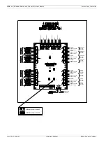
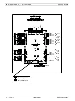
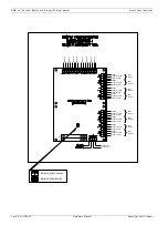
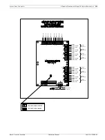
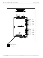
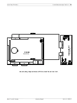
There are several terminal blocks and connectors on the Secure/Communication Card.
Detailed explanations are described below.
Reference Parallel Port : CN1
This is a parallel port utilized by the CPU. It is one of the communication links between the
CPU and the Secure/Communication Card. The communication cable is a 25 way ribbon cable
with one end a DB25 female connector and the other is a 26pin IDC connector.
Reference Serial Port: CN2
This is a serial port utilized by the CPU. It is one of the communication link between the CPU
and the Secure/Communication Card. The communication cable is a 9 way ribbon cable with
one end a DB9 male connector and the other is a 10pin IDC connector.
Reference Mains Power Fail: T2-1 & T2-2
This input allows you to monitor the power source status. When there is a power failure from
the source, it could trigger the common alarm output and register as a controller AC fail in the
View Activity. To utilize this feature, you will need to provide a dry contact output with nor-
mally close contact to this Mains Power Fail input.
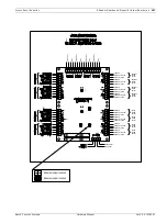
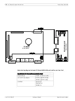
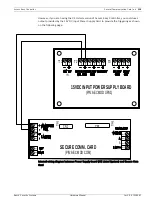
The UL Listed version of the Access Easy Controller uses the 18V DC input power supply card
that provides a Mains Power Fail output, this output could be terminated to the Mains Power
Fails on the Secure/Communication Card to monitor the status of the power source, as shown
in the following diagram.

