104
en | 4-Reader Boards and 8 Input/8 Output Boards
Access Easy Controller
Ver 2.0.0 | 2006.07
Hardware Manual
Bosch Security Systems
15.3.2
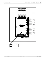
15VDC Input Termination
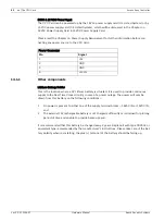
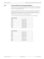
Reference: Terminal Strip T1
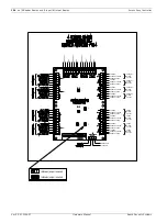
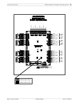
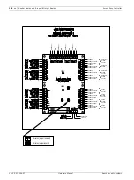
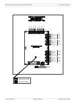
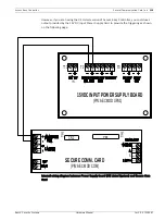
Terminals T1-1 and T1-2 are used to provide 15 Volt DC power to the 8-Input/Output card
board. Power is supplied from the DC output terminals of either the Power Supply card or
another interface card. The DC power is daisy-chained from the DC output terminals T2-3 (+)
and T2-4 (-) of the Power Supply card to terminals T1-1 (+) and T1-2 (-) of the first interface
card. From this card it is fed from terminals T1-3 (+) and T1-4 (-) to terminals T1-1 (+) and T1-
2 (-) of the next interface card. The diagram below shows the configuration of terminal strip
T1.
Refer to the Chapter entitle "The CPU Card" for additional details.
15.3.3
IDE Connectors
Reference: CN1 and CN2
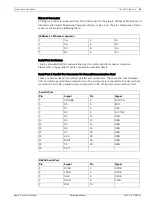
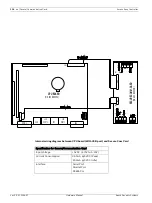
These are a pair of parallel-connected 40-pin IDE connectors. They are used as the data link
between the 8-Input/Output card board and other 4-reader board and or 8-Input/Output card
board. One connector is used to feed the IDE bus into the card from another interface card.
The second connector is used to extend the IDE bus to the next card. Each connector may be
used as either the incoming bus connector, or the outgoing bus connector.
15.3.4
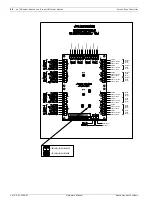
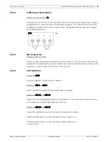
LED Indicators
Reference: LED9
This LED ind15 VDC power is present.
Reference: LED 1 to LED 8
LEDs 1 to 8 light whenever the associated relay is activated.


