148
en | Convertor Card
Access Easy Controller
Ver 2.0.0 | 2006.07
Hardware Manual
Bosch Security Systems
19.1.2
Jumper Setting
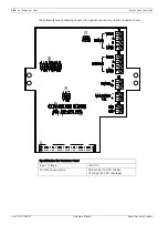
There are a few jumper blocks located on the card that need to be set. The table below shows
the Jumper Reference available for the Converter Card.
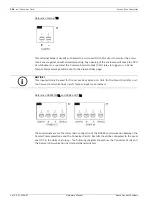
Reference : JP1
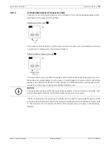
This is the end-of-line activation setting, RS485 requires the end of line resistor to be termi-
nated in the last Convertor Card in the daisy chain loop. We have simplified that, by providing
a jumper setting to activate the end-of-line
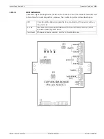
The diagram below indicates the location of the pin 1.
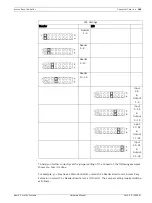
Reference : JP2
Each Convertor Card can support up to a max of 3 Reader Board or I/O Cards, therefore, it
needs to know which Cards are connected to it. For example, the Access Easy Extension unit
is fixed with 2 Reader Board and 1 I/O Card, you will need to identify the address of each
Cards and set the relevant Jumper on JP2. Each Jumper represents one Card.
In order to help you easily identify the Card number, the following table provides a reference
to the setting required on JP2 verse the Reader Board and I/O Cards in the enclosure.
Jumper Reference Table for Converter Card
Reference
Usage
JP1
End-of-Line Setting
JP2
Reader Board and I/O Present Setting
JP3
For Future Use
Setting
Jumper J1
Disable end-of-line setting
Enable end-of-line setting


