Access Easy Controller
Power Supply Requirement and Connection | en
153
Bosch Security Systems
Hardware Manual
Ver 2.0.0 | 2006.07
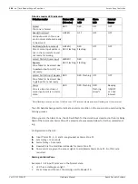
The data in the table are meant to be use as a general guide. It is the responsibility of the sys-
tem installer to determine the actual current consumption of the hardware that the external
battery is to support in order to provide continuous supply for a known period.
TIP:If a longer Backup time is desired, it is recommended that all the Readers takes its supply
from another external power supply unit with its own back-up battery.
For system that could not be contained within the Main Enclosure, such as a 10-Door Access
Control System, additional Access Easy Extension Unit(s) is added. In such case, the supply
to the cards in the Access Easy Extension Unit(s) are provided via its own 18V AC Input Power
Supply Card in the enclosure, which converts the AC input to DC output, or 15V DC Input
Power Supply Unit (15VDC input is only meant for .CE Listed system)
20.2
Connection in the Main Controller
The Main Controller could be powered up by either the 18V AC Input Power Supply Card or
the 15V DC Input Power Supply Card, depending on the model that have been ordered
(18VAC is meant for UL Listed system, 15VDC is meant for CE Listed system) The 15VDC out-
put from both the Power Supply Card is designed to supply power to all relays in all Reader
Boards and I/O Cards, within the Main Controller Enclosure. However, when additional
Reader Board and I/O Cards are installed in additional enclosures, called Access Easy Exten-
sion Unit, separate Power Supply Cards must be installed, and the current ratings of these
power supplies must be computed to be adequate
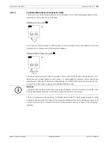
For UL Listed system, a power transformer(with a visual display indicating an AC power sta-
tus) that satisfy UL requirement is usually used to step down the standard AC voltage, sup-
plied from the public utilities, to the 18V supply. This power transformer should be able to
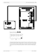
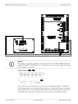
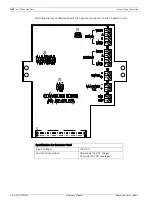
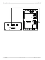
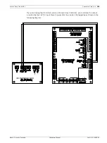
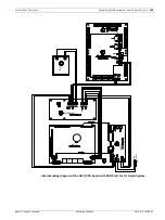
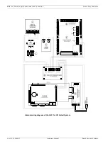
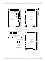
provide a continuous alternating current (ac) of 18V at 3A. The following diagrams show the
connection to the CPU Card and various Cards in the Main Controller for the UL Listed version
and CE Listed version.
i
NOTICE!
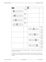
The table only takes into consideration the current consumption of the CPU, Convertor,
Reader Boards and I/O Cards and does not include current consumption of the locks and the
readers for each door. In practice, a separate power supply is used to provide supplies to
Locks.

