F 002 DG9 448
2018-02-01
|
Bosch Limited
Commissioning | ACS 151 | 11
en
i
The HP hose (red hose) should be connected to the
hose connection with the red identification sticker.
The LP hose (blue hose) should be connected to the
hose connection with the blue identification sticker.
Do not interchange the HP and LP hose connections.
459897_124Nkv
2
1
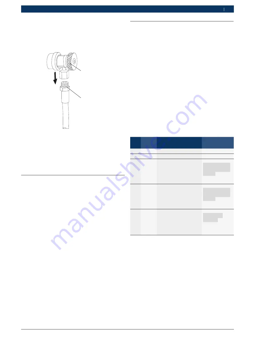
Fig. 7:
Fixing the couplers to the hoses
1 Coupler
2 O-ring
9.
Insert the coupler unto the other end of the hoses
and tighten. Ensure that the O-rings used for con-
necting the couplers to the hoses are properly
placed before tightening the coupler.
4.3
Powering on the ACS 151
1.
Move the ACS 151 to a flat, vibration-free surface.
2.
Apply the brake to prevent the unit from rolling away.
3.
Connect the power cable to the power inlet of the
ACS 151.
4.
Connect the power cable to the mains supply.
i
Refer chapter 9 for the specifications of power supply.
5.
Switch on the master switch.
"
The software version is displayed. After a couple of
seconds, the main menu is displayed.
There are two options available in the main menu:
R
A/C Services
R
Misc. Services
4.4
Filling the internal refrigerant
tank
Before the ACS 151 can be used, the internal refriger-
ant tank must be filled with R134a.
R134a can be procured from the local gas supplier. It is
normally stored and transported in tanks with connec-
tion fittings.
If cylinders without dip tube are used, the liquid ports
of the external cylinders should be connected to the
internal refrigerant cylinder. The cylinder should be
placed in an inverted position during the filling process.
If external cylinders with dip tube are used, the cylin-
ders can be placed in an upright position.
1.
Apply the brakes on the front wheel.
2.
Connect the adapter to the connection on the
external refrigerant tank.
3.
Connect the HP quick coupler of the ACS 151 to the
connecting adapter on the external refrigerant tank.
From the main menu, press the keys in the same order
as indicated in the following table:
Step Press
key...
To...
Remarks
1
1
Select
A/C SERVICES
--
2
2
Select
ADDITIONAL
--
3
2
Select
T-FILL
The message
CONNECT HP
TO EXT CYL-
INDER
is dis-
played. Execute
the instruction.
4
Enter
Open HP valve and close
OI valve.
The message
OPEN VALVE
OF EXT CYL-
INDER
is dis-
played. Execute
the instruction.
5
Enter
Open valve of external re-
frigerant tank
The message
OPEN HP
VALVE
is dis-
played. Execute
the instruction.
6
Enter
Close the oil valve
--


