background image


en


ACS 500  

AC Service Unit 

  Repair instructions

Summary of Contents for ACS 500 Series

Page 1: ...en ACS 500 AC Service Unit Repair instructions ...

Page 2: ...1 689 975 197 2006 09 22 Robert Bosch GmbH en ACS 500 ...

Page 3: ...trol display unit 11 5 3 12 Menu for calibration of force and pressure sensors 11 6 Calibrating force and pressure sensors 12 6 1 Calibrating force sensor 12 6 1 1 Refrigerant scale 12 6 1 2 Used oil fresh oil or UV contrast medium scale 12 6 2 Calibrating the pressure sensor 13 7 Updating firmware 13 8 Test 14 8 1 Control display unit function test 14 8 2 Checking the pressure switch 14 8 3 Check...

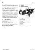
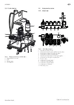
Page 4: ...many the type and scope of the tests are described in VDE 0701 0702 Part 1 The corresponding national regulations must be adhered to 2 Testing and resources General tool for electricians and mechanics Digital multimeter PC or Notebook Windows 2000 XP 9 pole Sub D cabel plug male female wiring 1 1 for udating the firmware Pipe sealant with PTFE e g RODI DOS PTFE from Würth Cleaning medium e g brake...

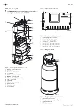
Page 5: ...9790 4 2 Fig 3 Valve block overview 1 Hose line for inlet and return 2 Solenoid valve for UV contrast medium injection phase 3 Solenoid valve OUT L for oil injection phase 4 Solenoid valve OUT R for filling phase 5 Solenoid valves OUT A for recovery recycling phase 6 Solenoid valves OUT B for vacuum phase 7 Pressure sensor 8 Connection to vacuum pump 9 Connection to processing unit 10 Connection t...

Page 6: ...RINTER COMPRESS PUMP J2 GND V 18 GND V 18 IN PMP IN CMP OUT HP IN 7 IN 1 IN 3 IN 4 IN 6 IN 8 PUMP OUT 1 OUT 3 OUT 4 OUT 6 OUT 7 OUT 8 LINE IN 200 mA T F2 TERRA TERRA F1 F3 459786_6 1 2 3 5 4 6 7 BU BN BU BN YE GN BU BN YE GN BU BN YE GN BU BN YE GN BU BN YE GN BU BN YE GN BU BN YE GN BU BN YE GN BU BN YE GN BU BN YE GN YE GN YE GN Fig 5 Actuation circuit board overview 1 Printer power supply acces...

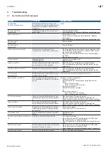
Page 7: ...vehicle A C system is greater than 1 6 bar Start and carry out recovery recycling phase Recovery phase timeout Maximum permissible time 240 min for evacuation of vehicle A C system re ached Read pressure on manometer Pressure is present Solenoid valves for recovery recycling phase do not open Check solenoid valves Check solenoid valve actuation No pressure present Vehicle A C system not tight or l...

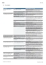
Page 8: ...cuit board have been swapped Check connection against connection dia gram wiring harness see Chap 12 2 The recovery and recycling phase ends prematurely or not at all Incorrectly calibrated or faulty pressure sensor Check pressure sensor see Chap 8 3 The gauge pressure rises after the recovery and recycling phase Valve pistons for the recovery and recy cling phase are leaking Check condition conta...

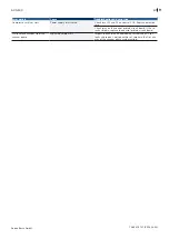
Page 9: ...d F3 on control PCB Replace defective fuse Check relay on the control printed circuit board If the re lay has blown replace the control printed circuit board White smoke escapes from the vacuum pump Aspirated ambient air Inspect the vehicle air conditioning system and ACS for leaks and repair Small quantities of smoke in the first min utes of the vacuum phase are permitted ...

Page 10: ...ameter menu 3358 Menu for resetting system parameters 2668 Menu for resetting counters 8266 Display menu for all counters 3282 Menu for entry of workshop address1 7732 Menu for setting the offset for the filling hoses2 3477 Menu for checking the control display unit 8272 Menu for calibration of force and pressure sensors2 1 Menus are also available in the main menu under Configuration 2 Menu is al...

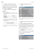
Page 11: ...hroughput quantity of refrigerant when filling the internal refrigerant flask with an external refrigerant flask Pump operating time Operating time of vacuum pump R134 filled Throughput quantity of refrigerant in filling phase 5 3 8 Display menu for all counters Displays all internal counters 5 3 9 Menu for entry of workshop address Input menu for the workshop address The workshop address can also...

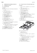
Page 12: ...cessfully completed i r r r r 6 1 2 Used oil fresh oil or UV contrast medium scale Procedure 1 Remove electronic compartment cover see Section 9 1 1 2 Connect mains connector 3 Turn on ACS 500 at master switch Initial message appears 4 Call up main Service menu 5 Enter password 1958 6 Confirm password with V 7 Call up Calibration menu item 8 Select menu item for the force sensor to be calibrated T...

Page 13: ...hin layer of pipe sealant to the quick release coupling screw thread 14 Screw quick release couplings onto hose lines and tighten Calibration complete r r r 7 Updating firmware Procedure 1 Start setup file e g pc77e0 exe from EDIS CD version 61 seeunder EDIS Software kdsoft ACS500 and carry out installation 2 With the 9 pole Sub D cabel plug male female wiring 1 1 connect the serial interface on t...

Page 14: ...tch for continuity Continuity Pressure switch OK No continuity Check connecting lead Replace pressure switch see section 9 8 e e i 8 3 Check pressure sensor Procedure 1 Plug in power plug 2 Switch on ACS 3 Remove quick release coupling from hose line LP 4 Open low pressure valve completely 5 Call up calibration and customer service menu see Section 5 6 Call up submenu 8439 see Section 5 2 The disp...

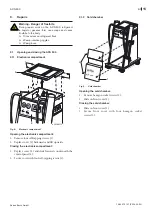
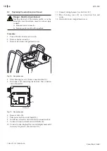
Page 15: ...1 1 2 3 Fig 8 Electronic compartment Opening the electronic compartment 1 Remove four self tapping screws 1 2 Replace cover 2 backwards and lift upwards Closing the electronic compartment 1 Replace cover 2 and slide forwards underneath the control panel 3 2 Secure cover with four self tapping screws 1 e e e 9 1 2 Cold chamber HP LP 459779 13 BOSCH ACS 400 2 1 Kg g min s R134a V Fig 9 Cold chamber ...

Page 16: ...nt cover 4 5 9 7 8 6 _ 1 8 1 2 3 Fig 10 Connection box 4 Place housing cover 1 from connection box 2 5 Disconnect all connecting leads from the actuation circuit board 3 459786_26 4 4 5 Fig 11 Connection box 6 Remove bolts 4 7 Take out actuation circuit board 5 8 Install new actuation circuit board in connection box 9 Secure actuation circuit board with bolts 4 10 Connect connecting lead for contr...

Page 17: ...ectingleads 3to10 control displayunit see Section 12 1 The following additional actions must be performed after the replacement Select national language Set date and time Enter workshop address Calibrate force sensors see section 6 1 Calibrate pressure sensor see section 6 2 9 3 2 Checking control display unit Procedure 1 Carry out function test see section 5 2 After successful test re attach elec...

Page 18: ...control and display unit 13 Secure connecting lead with cable tie 14 Calibrate force sensor see section 6 1 1 15 Place refrigerant flask on scale 16 Secure refrigerant flask with bolt see Fig 13 1 17 Remove coarse residue of pipe sealant on connecting thread of refrigerant flask for the hose lines and clean with a suitable cleaning medium e g brake cleaner 18 Apply a thin layer of pipe sealant to ...

Page 19: ... off ACS 500 at master switch 2 Remove mains connector 3 Remove electronic compartment and cold chamber covers 4 Close stop cocks and shut off valves on the refrigerant flask 459786_20 1 Fig 17 Solenoid valve connector 5 Remove all solenoid valve connectors 1 e e e e e 459790 12 2 3 4 5 6 8 7 9 Fig 18 Valve block 6 Remove hexagon bolts 2 with washers 7 Connect hose line 7 from refrigerant flask HP...

Page 20: ...sure sensor connecting lead to control display unit see section 12 1 21 Open stop cocks and shut off valves on the refrigerant flask 22 Attach covers 23 Calibrate pressure sensor see section 6 2 9 6 Replacing the pressure sensor Procedure 1 Turn off ACS 500 at master switch 2 Remove mains connector 3 Remove electronic compartment cover 4 Dismantle valve block see section 9 5 459786 28 1 2 Fig 21 P...

Page 21: ...ut on hose line 3 12 Connect hose line 3 e e i 13 Screw screw in socket 4 459786_25 8 Fig 24 Removal of vacuum pump 14 Remove hexagon bolts 8 15 Remove vacuum pump 16 Install new vacuum pump and secure 17 Remove coarse pipe sealant residue on screw in socket thread 4 and clean with a suitable cleaning medium e g brake cleaner 18 Apply a thin layer of pipe sealant to the screw in socket thread 4 19...

Page 22: ...essing unit condensertotherefrigerantflaskattheblueconnection on the refrigerant flask 6 Remove hose line at coarse filter on processing unit 7 Disconnect hose line at solenoid valve for oil drain 8 Disconnect electrical lead in vacuum pump connection box 9 Disconnect electrical lead in compressor connection box 10 Remove ground cable at the foot of the processing unit retaining plate 11 Remove co...

Page 23: ...oves Procedure 3 5 459786_31 4 Fig 26 Removal of pressure switch 1 Remove processing unit see Section 9 8 1 2 Unscrew pressure switch 3 while holding the hexagon nut 5 3 Removecoarsepipesealantresiduefromtheconnecting thread 4 and clean with a suitable cleaning medium e g brake cleaner 4 Apply a thin layer of pipe sealant to the connecting thread 4 5 Screw pressure switch into the connection and t...

Page 24: ...nect connecting lead from control display unit 6 Connect hose line 1 7 Remove hexagon bolts 5 8 Removeforcesensorwithpipeunionfromtheretaining plate 3 9 Remove hexagon bolts 7 and remove retaining plate 2 for pipe union from the force sensor i 459790 15 2 7 9 Fig 28 Assembly of force sensor 10 Place new force sensor on the work surface with the direction arrow 9 pointing upwards 11 Place retaining...

Page 25: ...Robert Bosch GmbH en 25 ACS 500 1 689 975 197 2006 09 22 10 Hose system diagram HP LP UV 1 2 3 4 5 6 7 8 9 R134a R134a UV abc def jkl mno tuv wxyz ghi pqrs 0 C 459790 9 Fig 30 Hose system diagram ...

Page 26: ...09 22 Robert Bosch GmbH en 26 ACS 500 11 Pneumatic circuit diagram F U F U F U F U M OUT A OUT I HP 1 34 bar 1 15 bar 0 10 bar 14 4 bar 16 bar 12 8 bar LP OUT S OUT B OUT R OUT L 459790 8 Fig 31 Pneumatic circuit diagram ...

Page 27: ... U N BU GN YE P GND V 18 IN PMP IN CMP OUT HP IN 7 IN 1 IN 3 IN 4 IN 6 459790 5 P U 11 9 15 bar ACS 400 16 19 5 bar ACS 450 4 5 3 2 6 7 8 9 1 10 OUT I 11 12 13 14 15 16 Fig 32 General terminal diagram 10 Master switch 11 Actuation circuit board 12 Scale for refrigerant 13 Scale for oil injection 14 Scale for oil drain 15 Scale for UV contrast medium injection 16 Battery 1 Control display unit 2 In...

Page 28: ...TERRA TERRA BU BN YE GN YE GN BU BN YE GN BU BN YE GN BU BN YE GN BU BN YE GN BU BN YE GN BU BN YE GN BU BN YE GN BU BN YE GN BU BN YE GN POM1 POM2 OUT 1 OUT 3 OUT 4 OUT 6 COMP BU BN YE GN LINE PROT 459790 7 OUT 7 OUT 8 Fig 33 Wiring harness connection to actuation circuit board 12 2 2 Connection to valve block 459790 6 POM2 OUT 1 OUT 4 OUT 3 POM2C OUT 1A OUT 8 Fig 34 Wiring harness connection to ...

Page 29: ...rt Bosch GmbH Automotive Aftermarket Test Equipment Franz Oechsle Str 4 D 73207 Plochingen www bosch com e Mail Bosch Prueftechnik de bosch com Printed in Germany Imprimé en Allemagne ACS 500 0 684 350 500 ACS 500 S1 0 684 350 501 ...

Reviews: