ACS 561 Service Manual
Robert Bosch GmbH
SP00D00517
2018-07-11
57
Electrical
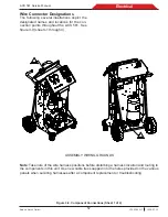
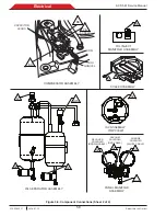
Wire Connector Designations
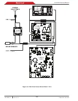
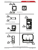
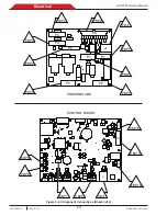
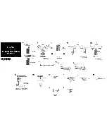
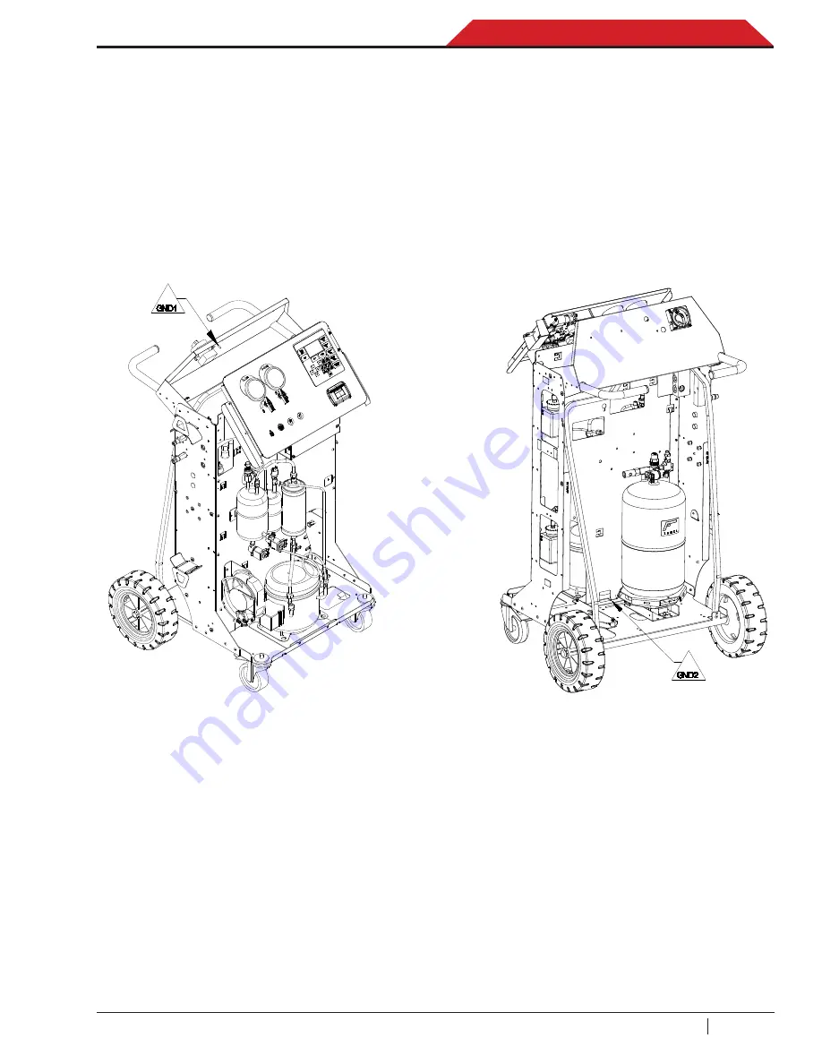
The following several illustrations depict the
designated names and locations for the con-
nection points throughout the ACS 561. See
figure 3-9 (sheets 1 through 4).
Figure 3-9. Component Connections (Sheet 1 of 4)
ASSEMBLY WIRING GROUNDS
Note
: Take note of the wire harness positions before disturbing a harness location and routing to
the components in this unit. Use new cable ties snapped into the holes provided on the various
panels when securing harnesses after a component replacement or troubleshooting.
Summary of Contents for ACS 561
Page 1: ...ACS 561 en Repair instruction A C Service Unit ...
Page 95: ......

