1 689 988 238
2012-11-06
|
Robert Bosch GmbH
Maintenance | ACS 651/751 | 125
en
9.
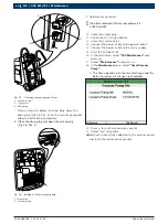
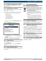
Attach the quick couplers to the 6m hoses.
459872_4lN
kv
2
1
Fig. 36: Fixing the couplers to the hoses
1. Coupler
2. O-ring
!
Do not use any tool to tighten the couplers.
i
Ensure that the O-rings (Fig. 36, Pos. 2) used for
connecting the couplers to the hoses are prop-
erly placed before tightening the couplers. Im-
proper placement of O-rings causes damage to the
ACS 651/751.
i
Do not reuse damaged O-rings. Order new O-rings in
case of damage.
459897_50Nkv
2
1
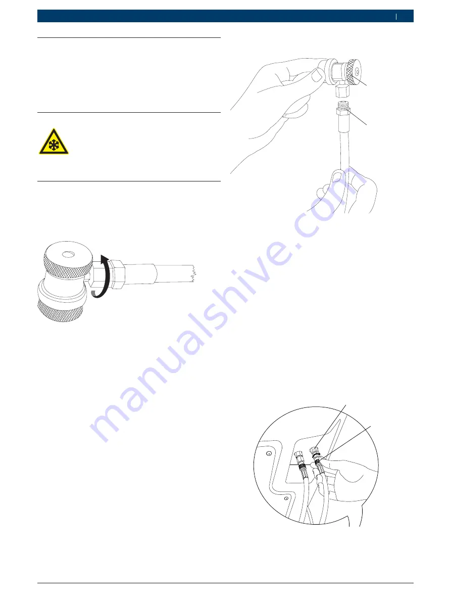
Fig. 37: Connecting the service hoses
1 Inline filter
2 Service hose
10.
Connect the power cable to the power socket.
11.
Connect the power cable to the mains supply.
7.9
Replacing the 3m hoses with 6m
hoses
To replace the 3m hose with the 6m hose, execute the
following procedure.
i
The order number for the 6m hoses is
F 002 DG1 458.
Warning - Risk of frostbite!
If refrigerant escapes, there is a risk of frost-
bite to the hands and body
.
Carefully disconnect hoses since they
contain pressurized refrigerant.
Use protective gloves.
Use protective goggles.
1.
Perform hose drain (see chapter 6.11).
2.
Switch off the mains supply.
3.
Disconnect the power cable from the mains supply.
4.
Disconnect the power cable from the power socket.
5.
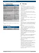
Detach the quick couplers from the service hoses.
459878_1Nkv
Fig. 35: Detaching the quick couplers from the hoses
6.
Disconnect the 3m hose from the inline filters.
i
Do not use any tools to loosen the hose connections.
7.
Connect the end connectors of the 6m hoses
(
Fig. 37, Pos. 2
) to the inline filters (
Fig. 37, Pos. 1
).
i
Ensure that the hoses are properly connected.
Improper hose connections might cause refrigerant
leakage resulting in frostbite.
8.
Tighten the hose connection.
i
Tighten the end connectors by hand. Do not use any
tools.

