


582819 | REV. A | 07.2018
Bosch Automotive Service Solutions Inc
ADS 325
|
User Manual
| 23 | en
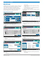
Oxygen (O2) Sensors
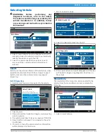
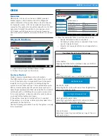
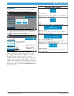
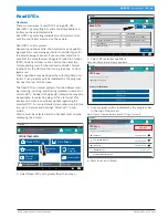
Mode 5 views O2 sensor monitor test results.
Generic OBDII
11:00
Readiness Mode 1
Description
Oxygen Sensor Tests (Mode 5)
Bank 1 Sensor 1
Maximum Sensor Voltage For
Test Cycle
Lean To Rich Sensor Threshold
Voltage
High Sensor Voltage For Switch
Time Calculation
Value
Min
Max
Units
V
V
V
Data Stream Mode 1
DTCs Modes 3, 4, 7, A
Freeze Frame Mode 2
02 Sensors Mode 5
Use Metric Units
Share
Help
?
May 31, 2018
Connected
1.275
0.000
0.003
0.003
0.003
0.000
0.000
1.275
1.275
ss03114
Mode 5 displays the average of the O2 sensor monitor
test results measured over a period of time. The param-
eters of this measurement vary between manufacturers.
It may be necessary to run the vehicle for a period of
time to allow the O2 sensors to fully warm up and begin
operating as intended.
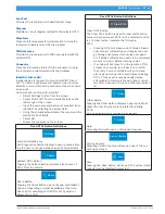
Oxygen (O2) Sensors Button Definitions
Other
Other Button
Tapping the Other button displays a pop-up link that
takes the user to more buttons.
Help
View Help
Selecting View Help will open an online user manual.
Use Metric Units
Use Metric Units
Selecting Metric Units will switch from English/Stan-
dard Units to Metric Units.
Use English/Standard Units
Use English/Standard Units
Selecting English/Standard Units will switch from
Metric Units to English/Standard Units.
Screen Capture
Screen Capture
Selecting Screen Capture will save a copy of the cur-
rent open screen.
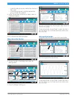
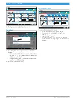
Non-Continuous Tests
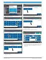
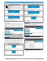
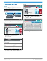
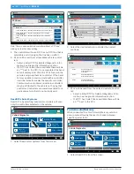
Mode 6 views onboard monitoring test results for non-
continuous monitor systems.
Generic OBDII
11:00
02 Sensors Mode 5
Special Tests Mode 8
DTCs Modes 3, 4, 7, A
Non-continuous Tests
Mode 6
Vehicle Info Mode 9
?
May 31, 2018
Use Metric Units
Share
Help
?
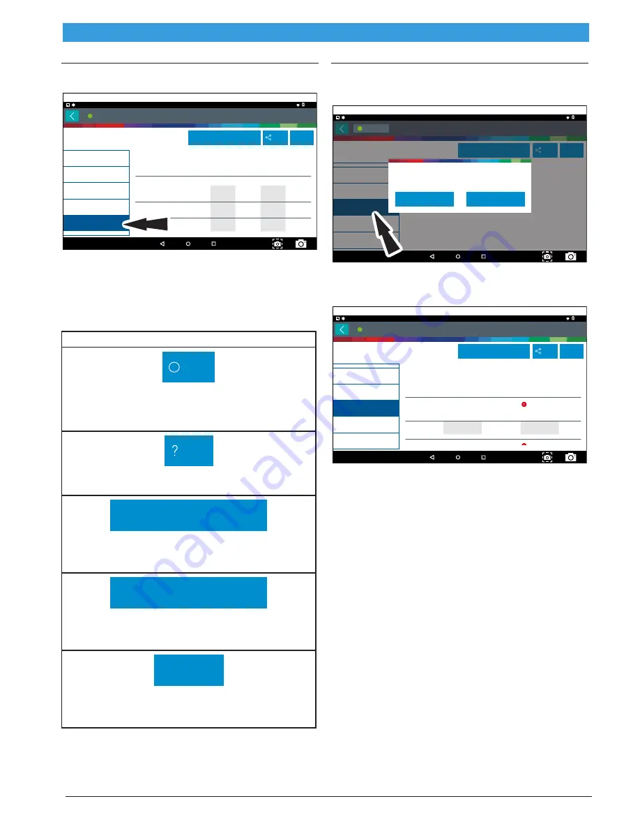
Component parameters may not be valid if Readiness Status is
'Not Ready'.
OK
Cancel
Connected
ss03115
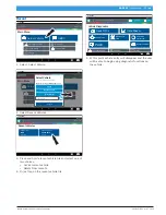
1. Select Non-Continuous Tests from the Generic OBDII
screen.
2. Follow the prompts on the screen.
Generic OBDII
11:00
02 Sensors Mode 5
Special Tests Mode 8
DTCs Modes 3, 4, 7, A
Non-continuous Tests
Mode 6
Vehicle Info Mode 9
?
May 31, 2018
Use Metric Units
Share
Help
?
Connected
ECU: ENGINE
Non-Continuously Monitored Tests
(Mode 6)
TID 1
TID 1
CID 1
TID 1
TID 2
TID 2
MIN
Failed
57581.0
5229
N/A
N/A
Failed
VALUE
MAX
UNITS
ss03116
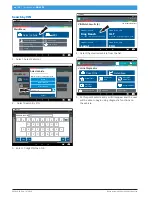
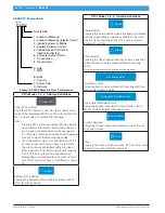
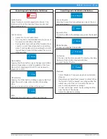
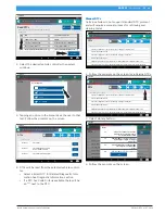
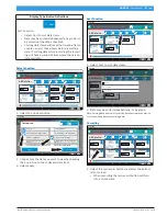
Non-Continuous Monitor Tests (Mode 6) are a pass/fail
test. Some examples are certain EVAP tests, catalyst,
and EGR. The following information is reported:
• ECU.
• TID (test identification) which indicates the sys-
tem monitor.
• CID (component identification) which indicates
the component tested and its test value.
• Minimum value, maximum value, and current value
for each non-continuous monitor supported.
• Pass or fail test results.
Each vehicle manufacturer assigns a code number to
their system monitors and components. Refer to the
vehicle manufacturers Mode 6 code chart to determine
the failure indicated by the TID and CID. If this chart is
not available, run an automated system test (AST) from
the DTC screen and select Mode 6. See Read DTCs
section for more information regarding steps to com-
plete that action.