

© 2018 Bosch Security Systems, Inc. 130 Perinton Parkway Fairport, NY 14450
F.01U.035.922 | 02 | 2018.05
| 2
Callout
Description
Callout
Description
1
4 in (10 cm) square
3
Double-gang box
2
Single-gang box
4
3.5 in (9 cm) octagon
This enclosure holds several Bosch and EDM input, output, and receiver modules.
1 | Overview
2 | Installation
NOTICE!
Failure to follow the mounting instructions can damage the enclosure.
1. Open by inserting a screwdriver into the two slots.
2. Use the mounting holes when installing to an elecrical box.
UP
3
1
4
NOTICE!
The wall tamper does not function when you install to an electrical box.
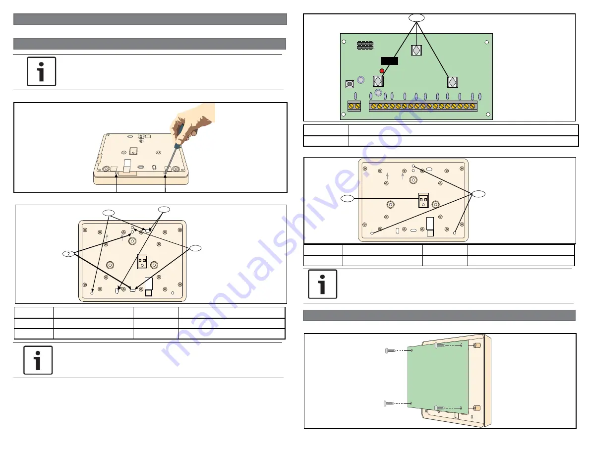
3. Install a 3-point module before installing the enclosure to the wall.
+AUX-
OUTPUT
TMPR R B G Y
OPTION
1
2 3
4 5
6 7
8
COM
COM
COM
COM
4 2 1
8
1
Callout
Description
1
Three-point mounting slots
4. Attach to the surface. Refer to the following illustration.
UP
1
1
Callout
Description
Callout
Description
1
Surface install holes
2
Wall tamper screw location
NOTICE!
Inserting a screw into the tamper bracket keeps the bracket and AE20 separate
when the screw is tightened, or when the AE20 is removed. For proper align-
ment, insert this screw last.
3 | Attaching
Install a module into the AE20. Refer to the following illustration.


