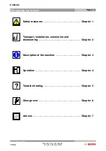

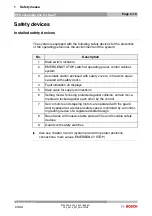
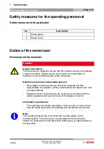
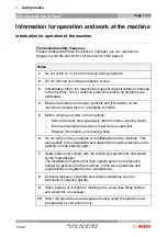
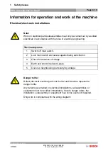


Contents
Page 1 / 5
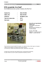
EPA assembly line for DaeP
Assembly Station
VPP 21
Station x
Station 2
Station 3
Station 4
Station 5
Station 6
Station 7
Station 8
Station 9
Station 10
Station 11
Station 12
Station 13
Station 14
Station 15
Station 16
Station 17
Station 18
Station 19
Station 20
Station 21
Station 22
Station 23
Station 24
Station 25
Station 26
Station 27
Station 28
Station 29
Station 30
Station 31
Station 32
Station 33
Station 34
Station 35
Station 36
Station 37
Station 38
Station 39
Station 40
Station 50
Station 60
Station 70
Station 80
Station 90
Station 100
Station 110
Station 120
Station 130
Station 140
Station 150
Station 160
Station 170
Station 180
Station 190
Station 200
Station 210
Station 220
Station 230
Station 240
Station 250
Station 260
Station 270
M.3000314.190_0843.195.960 /
V0.0_0613_EN_PA--ATMO2
Robert Bosch GmbH
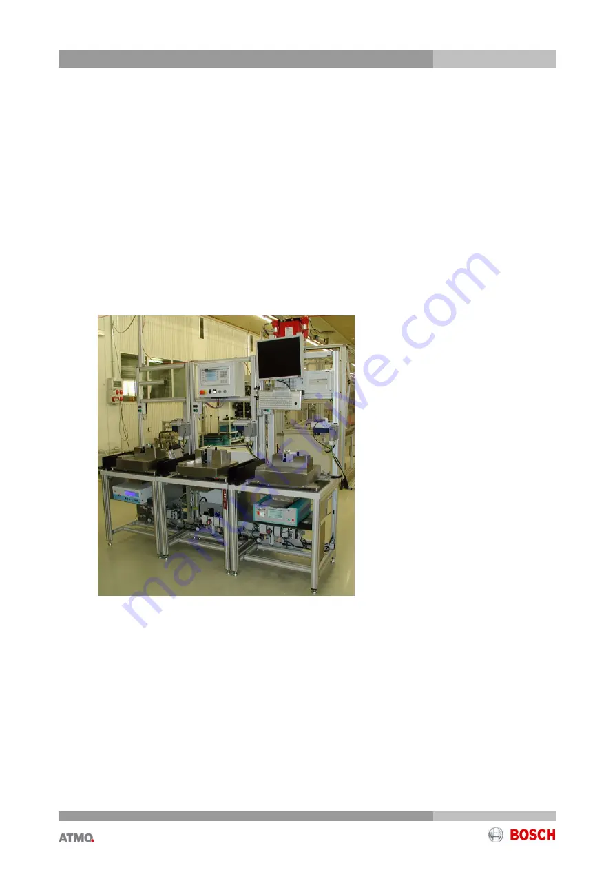
EPA assembly line DaeP
FA3 STATIONS 60--61--62: Leak Test / Dae Assy / Dae Flow Test
System No.
:
0843.195.960
Station No.
:
0843.195.961
Order No.
:
M.3000314.190
Year of construction
:
2013
Customer
:
DaeP
Robert Bosch Spain Madrid
Factory
,
S.A.
PA--ATMO2-- Automations
technical
Md Hnos García Noblejas, 19
E--28037 Madrid
Service: Dept. SGS,
Telephone: ++34 913 279 524
Telefax: ++34 913 279 610
These documents are only intended for the buyers of our machines and may not be copied or conveyed or
otherwise made available to a third party without written permission
.
(Law pertaining to copyright and related protective rights, Copyright law of 09.09.1965)
All rights with the Robert Bosch Spain Madrid Factory, including all patent applications.
Any right of disposal, such as the right of reproduction and passing on, with us.


