background image

AUTODOME IP starlight 7000i

Connection | en

55

Bosch Security Systems

Installation Manual

2021-03 | 1.2 |

13

Connection

13.1

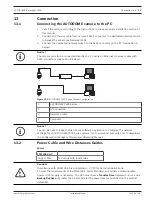
Connecting the AUTODOME camera to the PC

1.

Install the camera according to the instructions in the appropriate Installation section of
this manual.

2.

Connect an Ethernet cable from camera’s RJ45 connector to a dedicated network switch
to bypass the Local Area Network (LAN).

3.

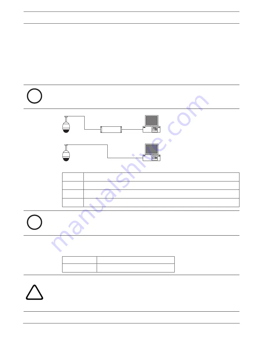
Connect the dedicated network switch to the RJ45 connector on the PC (see option A
below).

i

Notice!

The camera can also be connected directly to a PC using an Ethernet crossover cable with
RJ45 connectors (see option B below).

1

2

3

4

1

2

2

4

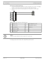
Figure 13.1: 

AUTODOME 7000 Series System Configuration

1

AUTODOME 7000 Series

2

IP Connection

3

Network Switch

4

Computer

i

Notice!

You can also use the Bosch Video Client software application to configure the network
settings for an AUTODOME 7000 Series camera. Go to www.boschsecurity.com to download
the Configuration Manager software and Operating Manual.

13.2

Power Cable and Wire Distances Guides

Power

115/230 VAC

Copper Wire

To comply with local codes.

!

Caution!

Compliance with EN50130-4 Alarm Standard – CCTV for Security Applications
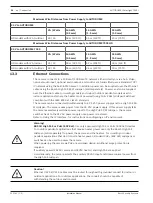
To meet the requirements of the EN50130-4 Alarm Standard, an ancillary uninterruptable
power (UPS) supply is necessary. The UPS must have a 

Transfer Time

 between 2–6 ms and a

Backup Runtime

 of greater than 5 seconds for the power level as specified on the product

datasheet.

Summary of Contents for AUTODOME IP starlight 7000i NDP?7512?Z30

Page 1: ...AUTODOME IP starlight 7000i NDP 7512 Z30 NDP 7512 Z30K en Installation Manual ...

Page 2: ......

Page 3: ...rs 26 9 3 Route Power through Intermediate Power Supply Box 30 9 4 Attach Pendant Arm to Power Supply Box 33 9 5 Make Connections in the Power Supply Box 34 9 6 Installing the VGA PEND WPLATE 35 9 7 Attach Pendant to Arm and Tighten 38 10 Installing the Roof Parapet and Pipe Mounts 40 10 1 Description 40 10 2 Route Wires and Attach Connectors 40 10 3 Attach Cover Door to Power Supply Box 45 10 4 I...

Page 4: ...4 en Table of contents AUTODOME IP starlight 7000i 2021 03 1 2 Installation Manual Bosch Security Systems 15 Maintenance 67 16 Technical data 68 17 Support services and Bosch Academy 69 ...

Page 5: ...uation which if not avoided could result in death or serious injury Caution Indicates a hazardous situation which if not avoided could result in minor or moderate injury i Notice Indicates a situation which if not avoided could result in damage to the equipment or environment or data loss 1 4 Important Safety Instructions Read follow and retain for future reference all of the following safety inst...

Page 6: ...e unit is operational only when the ON OFF switch is in the ON position The power cord is the main power disconnect device for switching off the voltage for all units When High PoE or PoE 820 3at is used to power the unit the power is provided over the Ethernet cable which is then the main power disconnect device for switching off the voltage for all units 10 Power sources Operate the unit only fr...

Page 7: ...NSTALL EXTERNAL INTERCONNECTING CABLES IN ACCORDANCE TO NEC ANSI NFPA70 FOR US APPLICATION AND CANADIAN ELECTRICAL CODE PART I CSA C22 1 FOR CAN APPLICATION AND IN ACCORDANCE TO LOCAL COUNTRY CODES FOR ALL OTHER COUNTRIES BRANCH CIRCUIT PROTECTION INCORPORATING A 20 A 2 POLE LISTED CIRCUIT BREAKER OR BRANCH RATED FUSES ARE REQUIRED AS PART OF THE BUILDING INSTALLATION A READILY ACCESSIBLE 2 POLE D...

Page 8: ...8 en Safety EN AUTODOME IP starlight 7000i 2021 03 1 2 Installation Manual Bosch Security Systems If a power adapter supplies power to the camera you must ground the adapter properly ...

Page 9: ...ter this unit has had its ground terminal connected properly to a ground source Disconnect the unit s input connectors from outdoor equipment before disconnecting the grounding terminal Follow proper safety precautions such as grounding for any outdoor device connected to this unit U S A models only Section 810 of the National Electrical Code ANSI NFPA No 70 provides information regarding proper g...

Page 10: ...vice has no user serviceable parts i Notice This is a class A product In a domestic environment this product may cause radio interference in which case the user may be required to take adequate measures i Notice Ce produit est un appareil de Classe A Son utilisation dans une zone résidentielle risque de provoquer des interférences Le cas échéant l utilisateur devra prendre les mesures nécessaires ...

Page 11: ...l or unintentional modifications not expressly approved by the party responsible for compliance shall not be made Any such modifications could void the user s authority to operate the equipment If necessary the user should consult the dealer or an experienced radio television technician for corrective action 1 6 Connection in Applications 24 VAC power source This unit is intended to operate with a...

Page 12: ...0 366 1329 Email repair us bosch com Customer Service Telephone 800 289 0096 option 3 Fax 800 315 0470 Email orders us bosch com Technical Support Telephone 800 289 0096 option 4 Fax 800 315 0470 Email technical support us bosch com Europe Middle East Africa and Asia Pacific Regions Contact your local distributor or Bosch sales office Use this link https www boschsecurity com xc en where to buy Mo...

Page 13: ... original packing carton if undamaged is the safest container in which to transport the unit and must be used if returning the unit for service Save it for possible future use 2 1 Parts List Quantity Component 1 AUTODOME IP starlight 7000i pendant camera 1 Desiccant silica gel bag 1 ESD zip bag 1 Safety and Unpacking Guide 4 MAC address labels 2 2 Tools Required Quantity Item For Mount Type Suppli...

Page 14: ...eparately from mount 1 Right angle NPS conduit connector 3 4 in 20 mm Mast pole mount with VGA PEND WPLATE No 1 Screwdriver medium straight blade Roof parapet Mount Pipe Mount No 1 Screwdriver No 1 Phillips Roof parapet Mount Pipe Mount No 1 Pipe wrench Roof parapet Mount Pipe Mount No 1 Barrel connector Roof parapet Mount Pipe Mount Only if installing a fiber optic model No The following table li...

Page 15: ...P starlight 7000i Unpacking en 15 Bosch Security Systems Installation Manual 2021 03 1 2 Quantity Product Part Number Size 4 Studs stainless steel corrosion resistant user supplied 6 4 mm 0 25 in to 8 mm 5 16 in ...

Page 16: ...perating temperature of the camera to go above the maximum If you install a camera in an enclosed area make sure that the operating temperature of the camera does not go above the maximum temperature The maximum operating temperature is 40 C 104 F for in ceiling models 55 C 131 F for pendant models Make sure that air circulates around the camera to supply cooling The following table lists the opti...

Page 17: ... Supply Boxes VGA ROOF MOUNT Power Supply Box and cover with 120 VAC transformer or with 230 VAC transformer VG4 A PSU1 VG4 A PSU2 Pipe Mount with one of the following Power Supply Boxes VG4 A 9543 Power Supply Box and cover with 120 VAC transformer or with 230 VAC transformer VG4 A PSU1 VG4 A PSU2 The following table lists the optional parts sold separately that you may need for attaching a Penda...

Page 18: ...age 35 Warning For units intended to be installed outdoors All wiring power and I O cabling connecting to the unit must be routed separately inside different permanently earthed metal conduits not supplied Warning To minimize the potential for corrosion on the housing use only Bosch hardware and mounts See number 5 Installation in a corrosive environment in the section Recommended Use of Your Came...

Page 19: ...lize the AUTODOME against strong winds Use the LTC 9230 01 Flat Roof Mount Adapter where appropriate This adapter is made specifically for AUTODOME roof applications Extreme Mount Applications Unique camera mounting applications that are impacted by extreme high winds heavy traffic or other conditions may require additional measures to stabilize the camera Contact a manufacturer that specializes i...

Page 20: ...en the camera zooms in on a target Use the pendant arm mount if possible This mount option provides the most stability for the camera Use guy wires to protect against strong winds if using the parapet mount Field of View Select a location and viewing angle that allows the flow of people to move across the camera s field of view Avoid motion that moves directly towards the camera Avoid locations th...

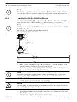
Page 21: ...using for no more than five 5 minutes Remove the bubble from a pendant housing 1 Using both hands apply a firm counterclockwise looking up at the dome rotational force on the pendant bubble assembly to set the bubble latch 2 Insert a small 2 mm straight blade screw driver into the release opening in the bubble trim ring to release the lock and then remove the screwdriver Figure 5 1 Remove the bubb...

Page 22: ...ese sections depending on the type of camera mount Remove bubble from in ceiling housing or Remove bubble from pendant housing 2 Locate the SD card slot highlighted in the figure below 3 Orient the card so that the side with the golden contacts faces away from the dome and towards the housing The contacts should be at the bottom as you hold the SD card 4 Slide the SD card into the slot Press down ...

Page 23: ...ty Systems Installation Manual 2021 03 1 2 7 Replacing the trim ring and bubble Replace the bubble in a pendant housing 1 Insert the bubble and trim ring assembly into the pendant housing 2 Rotate the assembly clockwise until it locks The latch mechanism makes a click when it locks ...

Page 24: ... lb pull out force is recommended The mounting material must be able to withstand this pull out force For example 19 mm 3 4 inch minimum for plywood 3 Secure the Power Supply Box to the mounting surface For a Wall installation Use four 4 corrosion resistant stainless steel studs not supplied Then proceed to Step 5 below For a Corner installation Secure the Corner Plate to the wall corner using fou...

Page 25: ...orner Mounts en 25 Bosch Security Systems Installation Manual 2021 03 1 2 Warning For units intended to be installed outdoors All wiring power and I O cabling connecting to the unit must be routed separately inside different permanently earthed metal conduits not supplied ...

Page 26: ...ily accessible 2 pole disconnect device with a contact separation of at least 3 mm 0 12 in must be incorporated Making the Connections i Notice Refer to the Connection page 55 chapter for wire specifications and distances 1 Route all video control and alarm wires through the earth grounded conduit fitting on the right side of the power box 2 Route the high voltage 115 230 VAC lines through the ear...

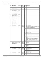
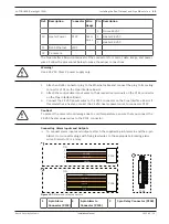
Page 27: ...nector P104 Pin Description Pin Description Pin Description 1 Alarm Out 1 1 Alarm in 3 1 Alarm Out 4 Normally Open 2 Alarm Out 2 2 Alarm in 4 2 Alarm Out 4 COM 3 Alarm Out 3 3 Alarm in 5 3 Alarm Out 4 Normally Closed 4 Alarm Ground 4 Alarm in 6 4 Earth Ground 5 Alarm in 7 5 Analog Alarm 1 6 Alarm Ground 6 Analog Alarm 2 7 Ground For in ceiling mount only Low Voltage TTL 3 3V can also be used 4 If ...

Page 28: ... NEUT Figure 9 2 Pendant arm power supply box 1 Ground Screw 7 P101 Connector Power In 120 VAC 220 VAC 2 From Harness Nexus cable bundle 8 P106 Connector Control In Out for external audio input and output 3 In Out 1 2 in 15 mm NPS Fitting 9 P105 Connector Audio to camera 4 Ethernet connector 10 Power In 3 4 in 20 mm NPS Fitting 5 P107 Connector 24 VAC to camera 11 Audio Input Output 3 4 in 20 mm N...

Page 29: ...nector Pin 1 Pin 2 Pin 3 Pin 4 Pin 5 Pin 6 Ground Grounding Screw P101 115 230 VAC or 24 VAC Power In Line NC Neutral P106 SERIAL COMMUNICATIONS CODE Audio IN Audio in signal ground CODE Audio IN Earth GND Ground Audio RXD Audio OUT TXD Audio OUT Audio out signal ground Signal GND Ground P107 24 VAC Power Arm Harness Camera 24 VAC Camera 24 VAC Earth Ground Heater 24 VAC Heater 24 VAC Table 9 1 Po...

Page 30: ...ation below depicts A VG4 PSU1 VG4 PSU2 Power Supply Box The main power supply connected to the P101 connector and to the grounding screw The 24 VAC power out wire connected to the P107 heater power connectors GND TXD RXD C C GND TXD RXD C C P101 1 2 3 6 5 4 3 2 1 6 5 4 3 2 1 6 5 4 3 2 1 6 5 4 3 2 1 6 5 4 3 2 1 6 5 4 3 2 1 6 5 4 3 2 1 6 5 4 3 2 1 6 5 4 3 2 1 6 5 4 3 2 1 6 5 4 3 2 1 6 5 4 3 2 1 6 5...

Page 31: ...he high voltage 120 230 VAC power and ground wires with sufficient slack to reach their connector terminal in the box but not so long as to be pinched by or to obstruct closing the cover door 3 Attach the supplied 3 pin power plug to the incoming high voltage power wires in the box Refer to connector P101 in the table above and to the image below for an illustration of these connections P101 1 2 3...

Page 32: ...or terminal in the box but not so long as to be pinched by or to obstruct closing the cover door 8 Attach the supplied 3 pin power plug to the incoming 24 VAC power wires in the box as illustrated below GND TXD RXD C C GND TXD RXD C C P101 1 2 3 6 5 4 3 2 1 6 5 4 5 4 3 2 1 6 5 4 5 4 5 4 6 5 4 5 4 6 5 4 5 4 5 4 6 5 4 6 5 4 6 5 4 3 2 1 3 2 1 6 5 4 3 2 5 4 3 2 3 2 5 4 3 2 P106 P105 P107 XF102 XF103 X...

Page 33: ... pin lever up and holding it i Notice Both Hinge Pins must be fully compressed to open unlock the hinges of the Pendant Arm and before proceeding to the next step 3 While continuing to hold the top hinge pin open and align the top and bottom hinges of the Pendant Arm to their mating points on the Power Supply Box See the illustration above 4 Once you have aligned the hinges release the top hinge p...

Page 34: ... and relay outputs connect the 4 pin Alarms Out the 6 pin Alarms In and the 7 pin Relay connectors from the Pendant Connector Harness to their mating connectors installed previously to the incoming alarm wires 6 Connect the 3 pin Power In Plug installed previously to its mating connector P101 on the left side of the box 7 Connect the incoming RJ45 video connector installed previously to its mating...

Page 35: ... Secure the Mounting Plate to the Corner Plate using the four 4 3 8 x 1 3 4 inch bolts and split lock washers supplied 2 For a Mast or pole installation The metal straps included with the Mast mount accommodate a pole with a diameter of 100 380 mm 4 15 in You must use a banding tool sold separately for a mast or pole installation In addition you must obtain a 3 4 in 20 mm right angle conduit conne...

Page 36: ...er up and holding it Note Both Hinge Pins must be fully compressed to open unlock the hinges of the Pendant Arm and before proceeding to the next step 3 While continuing to hold the top hinge pin open align the top and bottom hinges of the Pendant Arm to their mating points on the Mounting Plate 4 Once you have the hinges aligned release the top hinge pin to engage its mating hinge on the Mounting...

Page 37: ...stances 1 Route all incoming wires through one of the earth grounded conduits at the bottom of the Mounting Plate For a mast mount route all wires through the right angle conduit 2 Attach the water tight plug to the other conduit 3 Attach the grounding spade terminal item 1 below to one of the spade terminals inside the Mounting Plate Figure 9 11 Mounting Plate Inside Detail Ref Description 1 Grou...

Page 38: ...3 Connect the incoming serial communication wires to the 6 pin mating connector supplied with the VGA PEND WPLATE kit Refer to the Power Supply Box Connections table above for details 14 Attach the 6 pin serial communication mating connector to the Serial Communications cable cable 8 15 Connect the Earth ground wire if available to the crimp ring terminal inside the Mounting Plate Note The Earth g...

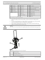
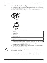
Page 39: ...sing hook on the Pendant Arm hinge pin allowing the dome to rotate around the pin 3 Rotate the dome housing down to a vertical position and gently push upward to engage the connector on top of the dome housing Caution If you feel any resistance when rotating the dome housing or when engaging the connector stop immediately and start over 4 Hold the Pendant housing in position while tightening the t...

Page 40: ...ntain the integrity of a Type 4X environment the connected equipment must have a Type 4X environmental rating In order to maintain the integrity of a Type 4 environment the connected equipment must have a Type 4 Type 4X Type 6 or Type 6P environmental rating 10 2 Route Wires and Attach Connectors Power wires must be routed to the left front side of the Power Supply Box through a separate electrica...

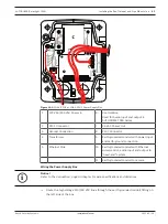
Page 41: ... for Audio input and output in AUTODOME 7000 Series 2 P101 Connector 7 24 VAC Power Out 3 Ground Connection 8 P107 Connector 4 Transformer 9 Earth grounded conduit with power input and earth ground connection 5 Ethernet Wire 10 Earth grounded conduit with Ethernet video control audio input and output to head end system 11 Earth grounded conduit to camera Wiring the Power Supply Box i Notice Refer ...

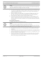
Page 42: ...mera will be mounted Attach the supplied 5 pin 24 VAC Dome plug to the wire ends inside the box Refer to connector P107 in the Power Supply Box Connections section below Wiring the Fiber Optic Model If installing a Fiber Optic model follow these steps i Notice Refer to the Connection page 55 chapter for fiber optic specifications For instructions on installing a fiber optic module into a power sup...

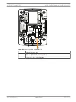
Page 43: ...s Installation Manual 2021 03 1 2 GND TXD RXD C C P101 P106 XF102 XF103 XF101 5 4 3 2 1 J103 J103 J103 J102 J101 LED HTR DOME 24V NC 24V FUSE FUSE FUSE FUSE Figure 10 2 Fiber Optic Ethernet Module installed 1 RJ45 Ethernet socket 2 Port for SFP module sold separately 3 Fiber Optic cable user supplied ...

Page 44: ...J101 J101 J101 J101 J101 J101 LED 6 5 4 3 2 1 GND GND GND TXD RXD C C XD XD XD XD HTR DOME FUSE FUSE FUSE FUSE FUSE FUSE FUSE FUSE FUSE FUSE FUSE FUSE FUSE FUSE FUSE FUSE FUSE FUSE FUSE FUSE LINE NC NEUT Figure 10 3 Power Supply Box Connections 1 Ground Screw 5 Power In 2 Transformer 115 230 VAC Modes 6 In Out 1 2 in 15 mm NPS Fitting 3 In Out to camera 7 Power In 3 4 in 20 mm NPS Fitting 4 24 VAC...

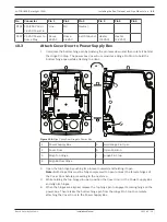
Page 45: ...oor GND TXD RXD C C GND TXD RXD C C FUSE FUSE FUSE 90 o HTR DOME LINE NC NEUT Figure 10 4 Align Cover Door Hinge to Power Box 1 Power Supply Box 5 Hold Hinge Pin Open 2 Cover Door 6 Open Position 3 Align Top Hinge 7 Hinge Pin Stop 4 Align Bottom Hinge 2 Open the top hinge by pushing its pin lever outward and holding it open Note Both Hinge Pins must be fully compressed to open unlock the female hi...

Page 46: ... be tightened securely 5 in 12 7 cm min Figure 10 5 Pipe Mount 1 Gasket 2 Flange 3 Cap 1 Before installing the Top Mounting Flange ensure there is an adequate opening in the ceiling or mounting structure for the wires to pass through 2 Secure the pipe Flange with supplied gasket to the ceiling or other supporting structure using four 4 10 mm 3 8 inch diameter fasteners i Notice Each fastener must ...

Page 47: ...nto the down pipe and tighten securely to prevent leaks Warning You must thread the Dome Cap onto the pipe until it is tight Failure to do so can result in damage or serious injury or death 10 5 Wire the Pipe Interface Board This section provides instructions for connecting wires and cables to the Pipe Interface Board as illustrated below Refer to the Connection page 55 chapter for cable and wirin...

Page 48: ... an AUTODOME 7000 Series camera remove this resistor P105 6 Data In Out P105 AWG 26 16 1 Biphase C For AUTODOME 7000 Series AUDIO IN Audio in signal ground 2 Biphase C For AUTODOME 7000 Series AUDIO IN 3 Earth Ground 4 RxD For AUTODOME 7000 Series AUDIO OUT 5 TxD For AUTODOME 7000 Series AUDIO OUT Audio out signal ground 6 Signal Ground 7 Alarms In EOLR Supervised 1 2 P104 AWG 26 16 7 Ground 6 Ala...

Page 49: ...pective terminals on the P105 connector on the Pipe Interface Board 3 Connect the 24 VAC power wires to the P101 connector on the Pipe Interface Board If this model has a heater connect the 24 VAC heater power wires to connector P107 Caution To protect the camera from damage due to cold temperatures ensure that you connect the 24 VAC heater power wires to the P101 connector Connecting Alarm Inputs...

Page 50: ...For in ceiling mount only Low Voltage TTL 3 3V can also be used 4 Connect the plugs to their mating connectors P103 and P102 on the Pipe Interface Board 1 To connect supervised alarms and relays attach the appropriate wires to their terminals on the P104 connector on the Pipe Interface Board see above 2 Insert the Pipe Interface Board into the down pipe and fasten the three 3 retaining screws to s...

Page 51: ... Dome Cap 2b Recessed Hinge Pin 2c Dome Connector 3 Rotate down to engage dome connector 4 Tighten the two 2 mounting screws to a minimum torque of 10 12 N m 90 105 in lbs 3 Drop the Pendant down slightly to engage the dome hook and hinge pin of the Dome Cap allowing the dome to rotate around the hinge pin 4 Rotate the dome housing down to a vertical position and gently push upward to engage the c...

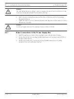
Page 52: ... Parapet Roof Mount 7 Tighten the three 3 10 mm 3 8 inch stainless steel hex bolts on the bracket to lock the Parapet Arm in position Caution Do not over tighten the bolts The maximum torque is 34 N m 25 ft lb 10 7 Make Connections in the Power Supply Box 1 Attach the earth ground wire to the grounding screw on the left side of the box 2 Connect the 24 VAC to Dome plug installed previously to its ...

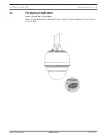
Page 53: ...nstallation en 53 Bosch Security Systems Installation Manual 2021 03 1 2 11 Finalizing installation Remove the plastic on the bubble After you complete all other installation steps remove the plastic material that is protection for the bubble ...

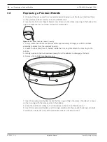
Page 54: ...ubble counterclockwise approximately 20 degrees until the bubble assembly releases from the pendant housing 4 Locate the four tabs item 1 below inside the trim ring that attach the trim ring to the bubble 5 Gently push each tab out and down away from the bubble to disengage the tabs 6 Remove the bubble from the trim ring 7 Insert the replacement bubble inside the trim ring and align the release ta...

Page 55: ... 3 4 1 2 2 4 Figure 13 1 AUTODOME 7000 Series System Configuration 1 AUTODOME 7000 Series 2 IP Connection 3 Network Switch 4 Computer i Notice You can also use the Bosch Video Client software application to configure the network settings for an AUTODOME 7000 Series camera Go to www boschsecurity com to download the Configuration Manager software and Operating Manual 13 2 Power Cable and Wire Dista...

Page 56: ...nt with the IEEE 802 3at class 4 standard The camera can be connected simultaneously to a 24 VAC power supply and to a High PoE 60 W midspan The camera uses power from the 24 VAC power supply If this power supply fails the camera seamlessly switches power input to the High PoE 60 W midspan The camera switches back to the 24 VAC power supply once power is restored Refer to Using the IP Interface fo...

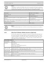
Page 57: ...ing requirements and limitations 13 4 Fiber Optic Ethernet Media Converter Optional The fiber optic media converter is designed to transmit 10 100 Mbps Ethernet signals over fiber optic cable using 10 100 Mbps Small Form factor Pluggable SFP modules The SFP modules are available as multi mode fiber MMF or single mode fiber SMF models with a single SC connector or dual fiber with an LC connector Re...

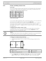
Page 58: ... the alarm is configured a short or a break in the alarm s circuit can trigger the tamper signal Configuring Supervised Alarms inputs 1 and 2 To configure Alarm 1 or 2 pin 5 or 6 for supervision you must install a 2 2 K end of line resistor in the circuit Then you program the alarms through Configuration to either Normally Open N O or Normally Closed N C i Notice Only Alarms 1 and 2 pins 5 or 6 ca...

Page 59: ...nector 2 Alarm 1 or 2 only Pin 5 or 6 4 Ground Pin 7 3 From Configuration select Interfaces Alarm Inputs select the number of the Alarm input and finally select N C See the table below for contact and condition details AUTODOME Programmed N C S Contact Alarm Condition Open Alarm Closed Normal Short Tamper Configuring Non supervised Alarms inputs 3 through 7 You can configure alarms 3 through 7 as ...

Page 60: ...he table below for contact and condition details AUTODOME Programmed N C Circuit Alarm Indication Open Alarm Closed Normal Alarm Outputs The camera incorporates two 2 types of alarm outputs one dry contact relay and three 3 open collector outputs or transistor outputs Configuring a Dry Contact Relay The dry contact relay acts like an on off switch It has a maximum voltage rating of 2 A 30 DC 1 Con...

Page 61: ...ld be complied with in all cases Max Input Voltage 1 Vrms Impedance 9 K Ω typical Shield Bare copper braid 95 coverage Internal gain level adjustment is available in case the signal level is too low Audio Line Output Specifications The following Line Output specifications should be complied with in all cases Typical Output Voltage 1 Vrms Impedance 1 5 K Ω typical Shield Bare copper braid 95 covera...

Page 62: ... Audio_Out RXD output terminal 2 Connect the audio line level output signal ground to the Audio_Out TXD output terminal Figure 13 6 Connections for audio over an Ethernet network 1 Audio_In C 7 AUTODOME Data In Out 2 Audio_In C 8 P105 P106 Connector 3 Earth Ground 9 Audio Out 4 Audio_Out RXD 5 Audio_Out TXD 6 Signal Ground i Notice Separate the audio cables from the AC power lines to avoid noise T...

Page 63: ...unit Reboot the unit After a Factory Default or firmware update reboot the unit if You cannot connect to the unit in the Web browser OR Configuration Manager or BVMS or similar software identifies the unit as Videojet Generic 4 Reboot the unit using one of the following methods In the web browser type the IP address and then reset without any punctuation Press the Enter key OR In Configuration Man...

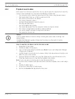
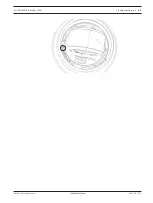
Page 64: ...out i Notice A factory default deletes all camera settings including passwords network settings and image settings Complete the following sequence of steps only if you have no other option to restore operation to the camera Steps to complete a hardware reset for all camera models 1 Apply power to the camera 2 Find the IP address of the camera 3 Log on to the camera using the web browser Note You c...

Page 65: ...AUTODOME IP starlight 7000i Troubleshooting en 65 Bosch Security Systems Installation Manual 2021 03 1 2 ...

Page 66: ...g instructions USA and Canada Telephone 800 289 0096 option 5 Fax 800 366 1329 Email repair us bosch com Customer Service Telephone 800 289 0096 option 3 Fax 800 315 0470 Email orders us bosch com Technical Support Telephone 800 289 0096 option 4 Fax 800 315 0470 Email technical support us bosch com Europe Middle East Africa and Asia Pacific Regions Contact your local distributor or Bosch sales of...

Page 67: ...h a cloth Use clean dry compressed air preferably from a spray can to remove any dust from the interior surface Warning Do not use alcohol based solutions to clean the bubble This will cause the surface to cloud and over time cause stress aging which makes the bubble brittle Cleaning the Bubble Exterior The exterior of the bubble is hard coated for extra protection If cleaning becomes necessary on...

Page 68: ...ght 7000i 2021 03 1 2 Installation Manual Bosch Security Systems 16 Technical data For product specifications see the datasheet for your camera available on the appropriate product pages of the Online Product Catalog at www boschsecurity com ...

Page 69: ...oschsecurity com xc en support Bosch Security and Safety Systems offers support in these areas Apps Tools Building Information Modeling Commissioning Warranty Troubleshooting Repair Exchange Product Security Bosch Building Technologies Academy Visit the Bosch Building Technologies Academy website and have access to training courses video tutorials and documents www boschsecurity com xc en support ...

Page 70: ...70 Support services and Bosch Academy AUTODOME IP starlight 7000i 2021 03 1 2 Installation Manual Bosch Security Systems ...

Page 71: ......
Page 72: ...Sicherheitssysteme GmbH Robert Bosch Ring 5 85630 Grasbrunn Germany www boschsecurity com Bosch Sicherheitssysteme GmbH 2021 Bosch Security Systems LLC 1706 Hempstead Road Lancaster PA 17601 USA 202103222045 ...

Reviews: