27
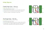
Single Stage Heat Pump
Example:
Bosch Inverter Ducted Split
▶
Ensure the system has a C-wire
▶
Ensure the pre-installed jumper wire remains between RH and R/RC
▶
Connect the R, C, Y1, O/B and G wires from the heat pump to R/RC, C, Y,
O/B and G terminals on the wall plate, respectively
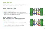
Single Stage Heat Pump
with Emergency Heat and Auxiliary Heat
Note:
W/E controls Emergency Heat output, and W2/AUX controls
Auxiliary Heat output.
▶
Ensure the system has a C-wire
▶
Ensure the pre-installed jumper wire remains between RH and R/RC
▶
Connect the R, C, W1, Y1, O/B and G wires from the heat pump to R/RC,
C, W/E, Y, O/B and G terminals on the wall plate, respectively
▶
Connect jumper wire between W/E and W2/AUX.
Wiring Diagrams
R/RC
R/RC
R/RC
R/RC
Heat pump systems
Heat pump systems are specialty designed to be able to provide heating and
cooling using a single compressor, a reversing valve, and a fan.
Summary of Contents for BCC100
Page 19: ...19 Choose Comfort Choose Bosch ...
Page 30: ...30 30 ...


