background image

4

 |


Installation Instructions

Bosch Climate 5000 Series 24 Volt Interface (06.2022)

1     Key to Symbols and Safety Instructions

1.1     Key to Symbols


Warnings


      Warnings in this document are identifi ed by a 

warning triangle printed against a grey background.
Keywords at the start of a warning indicate the type and seriousness  
of the ensuing risk if measures to prevent the risk are not taken.

The following keywords are defi ned and can be used in this document:


DANGER 

indicates a hazardous situation which, if not avoided, will result 

in death or serious injury.


WARNING

 indicates a hazardous situation which, if not avoided, could 

result in death or serious injury.


CAUTION


indicates a hazardous situation which, if not avoided, could 

result in minor to moderate injury.


NOTICE 

is used to address practices not related to personal injury.

Important information


   This symbol indicates important information where

there is no risk to people or property.

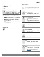
1.2     Safety Instructions


   Read this manual carefully before installing or operating your new 24 

Volt Interface Adapter. Make sure to save this manual for future 
reference.


WARNING: IMPROPER OPERATION  


Installation must be performed in accordance with the 
requirement of NEC and CEC by authorized personnel only.


WARNING: HAZARDOUS VOLTAGE


All wiring must be rated for the control box amperage 
rating.


All wiring installed must meet general industry standards 
and practices. 


WARNING: FIRE, EXPLOSION  


Do not install adapter near flammable liquids or gases.


WARNING: PERSONAL INJURY  


Wear appropriate personal protection equipment (PPE) 
when installing or servicing.


WARNING: ELECTRICAL SHOCK HAZARD  


Do not operate the unit with wet hands, as this could lead 
to electrical shock.


NOTICE: 


When connecting to the outdoor unit, shielded wire 
must be used and grounded at one end only to reduce 
Electromagnetic interference (EMI).


WARNING:  


This product can expose you to chemicals including Lead 
and Lead components, which are known to the State 
of California to cause cancer and birth defects or other 
reproductive harm. For more information go to 

www.

P65Warnings.ca.gov

.

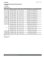
Summary of Contents for BMS500-AAS012-0AHWXB

Page 1: ...r and per the instructions in the installation manual Improper installation can cause water leakage electrical shock or fire In North America installation must be performed in accordance with the requirement of NEC National Electric Code and CEC Canadian Electric Code by licensed and qualified personnel only Only contact a licensed contractor for repair or maintenance of this unit ...

Page 2: ...2 Installation Instructions Bosch Climate 5000 Series 24 Volt Interface 06 2022 ...

Page 3: ...Key to Symbols 4 1 2 Safety Instructions 4 2 Dimensions 5 3 Clearances 5 4 Installation 6 4 1 Preparation 6 4 2 Installation Process 6 5 Applications 7 5 1 Application 1 7 5 2 Application 2 9 6 Control Logic 10 6 1 Connector 10 6 2 Mode Setting 10 6 3 Fan Speed Setting 10 7 Dip Switch Configuration 10 7 1 Dip Switch Definitions 10 8 Error Codes 12 ...

Page 4: ... Safety Instructions Read this manual carefully before installing or operating your new 24 Volt Interface Adapter Make sure to save this manual for future reference WARNING IMPROPER OPERATION Installation must be performed in accordance with the requirement of NEC and CEC by authorized personnel only WARNING HAZARDOUS VOLTAGE All wiring must be rated for the control box amperage rating All wiring ...

Page 5: ...es 24 Volt Interface 06 2022 2 Dimensions Figure 1 220mm 8 7 32mm 1 3 176mm 6 9 15mm 0 6 200mm 7 8 283mm 11 1 63mm 2 5 3 Clearances This interface must be installed indoors in an area free from drips and moisture Figure 2 Right Wrong 150mm 5 9 150mm 5 9 ...

Page 6: ... space required around the product is 7 180 mm 2 Mount the back plate of the 24V INTERFACE on the wall Mount the 24V INTERFACE vertically and fasten the back plate to the wall with 3 screws M4 x20 and anchors see Fig 4 Figure 4 Back plate Screws M4 20 Place the unit on a flat surface Be careful not to distort the back plate of the 24V INTERFACE by over tightening the screws When installed verticall...

Page 7: ...ted 230V BMS500 AAU018 1AHWXC 8 733 956 177 Minisplit 18kBTU Universal Wall Mounted 230V BMS500 AAU024 1AHWXC 8 733 956 178 Minisplit 24kBTU Universal Wall Mounted 230V BMS500 AAU006 1AHWXC 8 733 956 181 Minisplit 6kBTU Universal Wall Mounted 230V BMS500 AAU030 1AHWXC 8 733 956 182 Minisplit 30kBTU Single Zone Wall Mounted 230V BMS500 AAU036 1AHWXC 8 733 956 184 Minisplit 36kBTU Single Zone Wall M...

Page 8: ... 6 Thermostat 70 Temperature Sensor to be placed at indoor unit air intake Please connect thermostat G to 24V interface G as default Make sure the power supply is correct For Wall Mounted unit the up down swing louver and the display on off function is available with the wireless remote control ...

Page 9: ...kBTU Universal Cassette 230V BMS500 AAU048 1AHCXC 8 733 956 188 Minisplit 48kBTU Universal Cassette 230V Ducted BMS500 AAU036 1AHDXB 8 733 953 106 Minisplit 36kBTU Universal Ducted 230V BMS500 AAU048 1AHDXB 8 733 953 107 Minisplit 48kBTU Universal Ducted 230V BMS500 AAU060 1AHDXB 8 733 953 108 Minisplit 60kBTU Universal Ducted 230V Table 5 Cassette Sizes 36K 48K Ducted 36K 60K Wiring Figure 7 Ther...

Page 10: ...E must be configured to operate properly with the system components with which it is installed To successfully configure the system move the Dip Switches to match the components and functions used 7 1 Dip Switch Definitions Figure 8 SW2 SW3 SW4 SW1 Dip Switch 1 1 Used to turn ON or OFF the diagnostic code display LED on the control board of the 24V Interface SW1 1 Result Note ON Display on OFF Displ...

Page 11: ...3 1 Dry is used for thermostats with a Dry Function output An auxiliary heater is used on the Ducted Indoor Units to control a secondary Heat Source SW3 1 Result Note ON Dry OFF Aux heater Default Table 13 Dip Switch 3 2 Used to increase the compressor frequency in case the set point has not been reached after 1 hour or 3 hours of operation SW3 2 Result Note ON 1h OFF 3h Default Table 14 Dip Switc...

Page 12: ...T4 malfunction F2 Condenser coil temperature sensor T3 malfunction F3 Condenser coil temperature sensor T5 malfunction F4 Outdoor unit EEPROM parameter error F5 Outdoor fan speed error F6 T2b sensor error P0 Inverter module IPM malfunction P1 Over voltage or under voltage protection P2 Compressor top high temperature protection OLP P3 Low ambient temperature cut off in heating P4 Compressor drive m...

Page 13: ... 13 Installation Instructions Bosch Climate 5000 Series 24 Volt Interface 06 2022 NOTES ...

Page 14: ...14 Installation Instructions Bosch Climate 5000 Series 24 Volt Interface 06 2022 NOTES ...

Page 15: ... 15 Installation Instructions Bosch Climate 5000 Series 24 Volt Interface 06 2022 NOTES ...

Page 16: ... 65 Grove St Watertown MA 02472 Tel 866 642 3198 Fax 603 965 7581 www bosch thermotechnology us BTC 769103310 B 06 2022 Bosch Thermotechnology Corp reserves the right to make changes without notice due to continuing engineering and technological advances ...

Reviews: