


|
9
Installation Instructions
Bosch Climate 5000 Series 24 Volt Interface (06.2022)
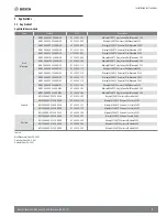
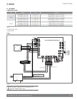
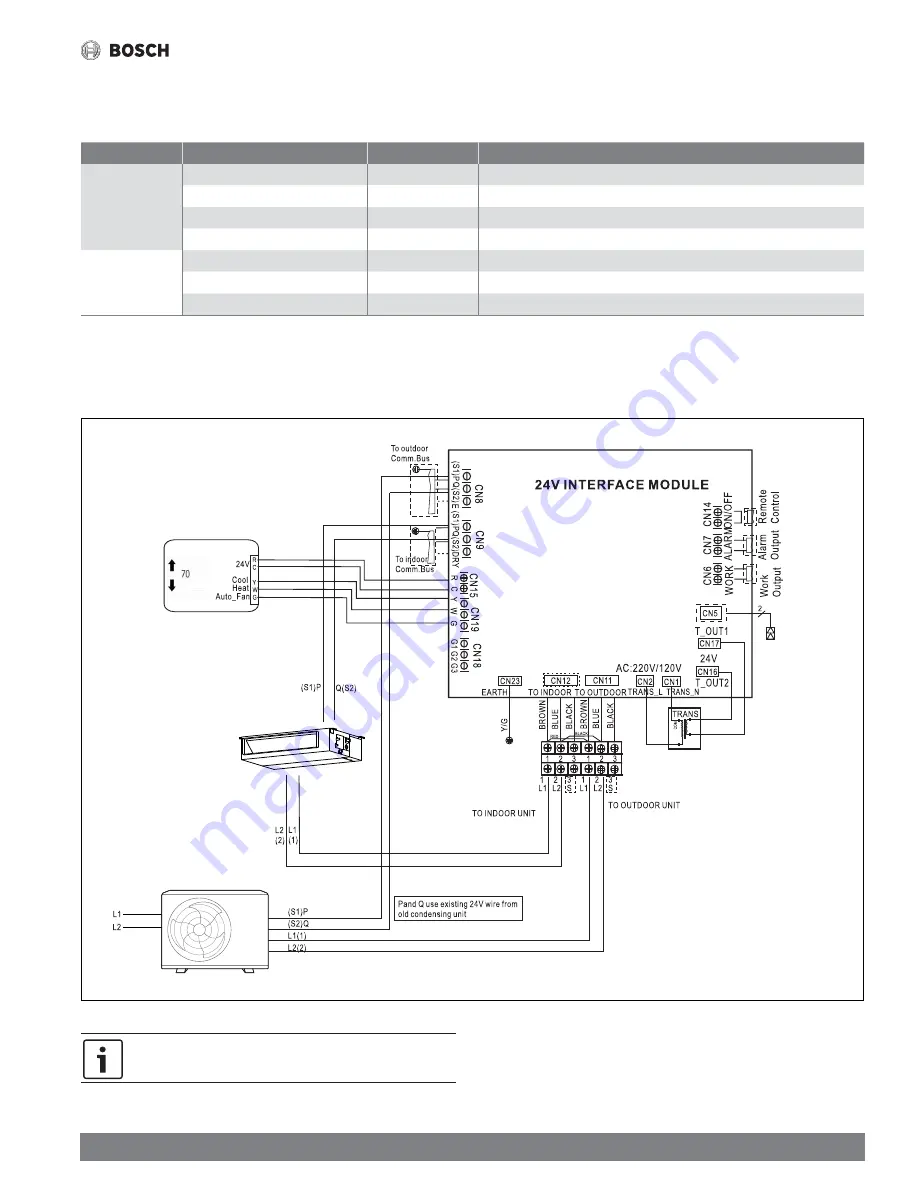
5.2 Application 2
Applicable Indoor models
Type
Model #
Part #
Description
Cassette
BMS500-AAU036-1AHCXB
8-733-953-113
Minisplit 36kBTU Universal Cassette 230V
BMS500-AAU048-1AHCXB
8-733-953114
Minisplit 48kBTU Universal Cassette 230V
BMS500-AAU036-1AHCXC
8-733-956-187
Minisplit 36kBTU Universal Cassette 230V
BMS500-AAU048-1AHCXC
8-733-956-188
Minisplit 48kBTU Universal Cassette 230V
Ducted
BMS500-AAU036-1AHDXB
8-733-953-106
Minisplit 36kBTU Universal Ducted 230V
BMS500-AAU048-1AHDXB
8-733-953-107
Minisplit 48kBTU Universal Ducted 230V
BMS500-AAU060-1AHDXB
8-733-953-108
Minisplit 60kBTU Universal Ducted 230V
Table 5
Cassette (Sizes 36K~48K)
Ducted (36K~60K)
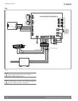
Wiring
Figure 7
Thermostat
T
e
mperature
Sensor
(to be placed
at indoor unit
air intake)
Please connect thermostat G to 24V interface G as default.
Make sure the power supply is correct.
Summary of Contents for BMS500-AAS012-0AHWXB
Page 2: ...2 Installation Instructions Bosch Climate 5000 Series 24 Volt Interface 06 2022 ...
Page 13: ... 13 Installation Instructions Bosch Climate 5000 Series 24 Volt Interface 06 2022 NOTES ...
Page 14: ...14 Installation Instructions Bosch Climate 5000 Series 24 Volt Interface 06 2022 NOTES ...
Page 15: ... 15 Installation Instructions Bosch Climate 5000 Series 24 Volt Interface 06 2022 NOTES ...


