8 |
Bosch Buderus SSB800SA | SSB1000SA | SSB1000TL Boilers Control Operations Guide
01.2020 | Bosch Thermotechnology Corp.
Data subject to change
4 Boiler Cascade Settings
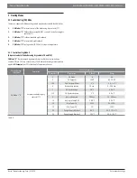
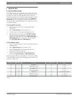
Number
Parameter Name
Description
Default
Min
Max
73
Boiler Address
Set boiler address i.e. Stand-Alone, Managing, Dependent 1....7
MANAGING
0
16
156
Permit Emergency Mode
Enable
Emergency Mode
in a multiple boiler cascade installation to ensure that any dependent boiler can operate
independently should communication with the managing boiler be interrupted or the managing boiler loses
communication with the supply sensor. The boiler will operate at a predetermined
Emergency Setpoint
which is
set using Parameter #157.
YES
NO YES
157
Emergency Setpoint
Emergency Setpoint
is the
fi
xed set point which a boiler will operate at within a cascade installation if that boiler
has lost communication with the Managing boiler or the Managing boiler loses communication with the supply
sensor. Parameter #156 must be “Yes” on each dependent boiler and
Emergency Setpoint
set for the desired
Emergency Temperature at which the boiler is to operate.
158 °F
68 °F
194 °F
158
Delay Per Start Next Blr
See
Hyst Down Start Boiler
.
1275 sec.
0 sec.
1275 sec.
159
Delay Per Stop Next Blr
See
Hyst Up Stop Boiler
.
1275 sec.
0 sec.
1275 sec.
160
Delay Quick Start Next
See
Hyst Down Quick Start
.
400 sec.
0 sec.
1275 sec.
161
Delay Quick Stop Next
See
Hyst Up Quick Stop
.
240 sec.
0 sec.
1275 sec.
162
Hyst Down Start Boiler
If the system temperature is
Hyst Down Start Boiler
degrees below the system set point the boilers are started at
intervals of
Delay Per Start Next Blr
.
9 °F
0 °F
72 °F
163
Hyst Up Stop Boiler
If the system temperature is
Hyst Up Stop Boiler
degrees above the system set poin tthe boilers are stopped at
intervals of
Delay Per Start Next Blr
.
3.6 °F
0 °F
72 °F
164
Hyst Down Quick Start
If the system temperature is
Hyst Down Quick Start
degrees below the system set point the boilers are started at
intervals of
Delay Quick Start Next
.
18 °F
0 °F
72 °F
165
Hyst Up Quick Stop
If the system temperature
Hysteresis Up Quick Stop
degrees is above the system set point the boilers are stopped
at intervals of
Delay Quick Stop Next
.
7.2 °F
0 °F
72 °F
166
Hyst Up Stop All
If the system temperature is
Hyst Up Quick Stop
degrees above the system set point the boilers are stopped at
intervals of
Delay Quick Stop Next
.
14.4 °F
0 °F
108 °F
167
Number Of Boilers
The amount of boilers in the cascade.
1
1
8
168
Power Mode
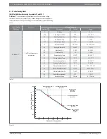
Power mode 0: Power control disabled, each boiler modulates based on the system setpoint.
Power mode 1: Power control algorithm to have a minimum amount of boilers active.
Power mode 2: Power control algorithm to have a maximum amount of boilers active.
Power mode 3: Power control algorithm to have a balanced amount of boilers active.
2
0
3
169
Max Setp Offset Down
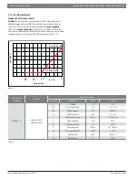
In order to achieve the desired Target System Supply Temperature during a call for heat the boilers may need to
operate at temperatures greater than or less than the desired Target System Supply Temperature. The operating
range in which the boilers are allowed to adjust the individual boiler supply temperatures is de
fi
ned by the
Max Setp
Offset Down
and
Max Setp Offset Up
(parameter #170) values. Each dependent boiler will display a “Calculated
Setpoint” temperature on the display which will be within this Off set Range either above or below the overall Target
System Supply Temperature.
0 °F
0 °F
72 °F
170
Max Setp Offset Up
See Parameter #169 for explanation of
Max Setp Offset Down
and
Max Setp Offset Up
.
36 °F
0 °F
72 °F
171
Start Mod Delay Fact
The Managing boiler will calculate the difference between the System Target Setpoint and the measured System
Supply Temperature once a period of time equal to
Delay Period Start Next Boiler
x
Start Modulation Delay
Factor
has passed.
20
0
255
172
Next Boiler Start Rate
The percentage of power a boiler must reach before the Managing boiler will begin the process of bringing on the
next boiler within the cascade. See Parameter#158 for further information on the amount of time which must pass
at this power percentage before the next boiler in the cascade rotation is enabled.
80%
10%
100%
173
Next Boiler Stop Rate
The percentage of power a boiler must reach before the Managing boiler will begin the process of turning off the last
boiler enabled within the cascade rotation sequence. See Parameter #159 for further information on the amount of
time which must pass at this power percentage before a boiler is turned off.
25%
10%
100%
174
Boiler Rotation Interval
Number of days selectable.
5 DAYS
0 DAYS
30 DAYS
175
First Boiler To Start
First boiler in cascade that will start.
1
1
8
180
Pwr Mode 2 Min Power
Minimum average burner power setting.
20%
0%
100%
181
Pwr Mode 2 Hysteresis
Hysteresis for the minimum average boiler power setting.
40%
0%
100%
182
Post-Pump Period
Factory setting - Do Not Change
N/A
N/A
N/A
Table 3


