background image

48

en | 

Carephone 61

F.01U.239.30x | V1 | 2011.06

User Manual

Bosch Security Systems

A.5

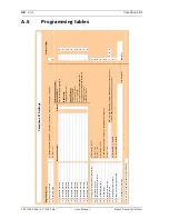
Programming tables

01

Language selection

0 = synthetic speech disabled, 1 = German, 2 = Dutch, 3 = French, 4 = English, 5 = Spanish

03

Radio jamming

0 = off, 1 = on

0

Destination number

11

Destination number 1

0

12

Destination number 2

0

13

Destination number 3

0

14

Destination number 4

0

15

Destination number 5

0

16

Destination number 6

0

17

Destination number 7

0

18

Destination number 8

0

19

Destination number 9

0

10

Destination number 10

0

23

Waiting time for repeated emergency call 

0...99 minutes, 0 = off

0

24

Confirmation with call

0 = off, 1 = on

0

25

Radio transmission monitoring

0 = off, 1 = on

0

26

Call back waiting time

0...9 minutes, 0 = off

0

28

Call forwarding

0 = forwarding to another number, 1 = forwarding to a telephone.

0

29

Hear/speech impaired

0 = off, 1 = on

0

30

Device number

1248

32

Call progress tones audible

0 = not audible, 1 = audible

0

33

Speak / Listen command audible

0 = not audible, 1 = audible

1

34

Personal voice recording

max 6 seconds

41 to 45 : refer to the user manual of the IP Module

(empty)

ANT: 4 digits; RB2000: 6/12 digits, depending on monitoring centre;

numbers 0000, 9998, 9999 and 999999 may not be used!

Carephone 61 Settings

Factory settings

Programming step

Enter destination number:

Phone numbers:

max. 22 characters: digits, B, D

IP addresses:

12 digits, without dot

Choose Protocol:

0 = Bosch protocol

1 = TTnew+ protocol

3 = CPC protocol

4 = to phone with acknowledgement

5 = to phone without acknowledgement

7 = BS8521 protocol

9 = RBIP protocol

Protocol

Summary of Contents for Carephone 61

Page 1: ...Carephone 61 CRS H61M xx en User Manual ...

Page 2: ......

Page 3: ... 1 Light signals 10 4 4 2 Sound signal in synthetic speech disabled mode 11 4 4 3 Local voice announcements from the unit 11 5 Installation 12 5 1 Installation recommendations 12 5 2 Placing the Carephone 61 12 5 3 Connecting the Carephone 61 13 5 3 1 PSTN or GSM connection 13 5 3 2 IP connection 14 5 3 3 VoIP connection 14 5 3 4 Connection configuration 14 5 4 Deinstallation 14 6 Programming 15 6...

Page 4: ...ction 29 7 5 microSD memory card 29 7 5 1 Installing the microSD memory card 30 7 5 2 Programming with the microSD memory card 32 8 Operation 34 8 1 Emergency Call to a Monitoring Centre 34 8 2 Emergency Call to a Private Phone 34 8 3 Taking Phone Calls 36 9 Maintenance 37 9 1 Cleaning 37 9 2 Battery disposal 37 9 3 Replacing the backup battery 38 A Appendix 42 A 1 Technical specifications 42 A 2 ...

Page 5: ...telephones This will impair the reception of signals from the wireless transmitter Use only original equipment for cables and power supply Any other power adapter could damage the unit Electrolytes or gases may be emitted from the battery should it leak under exceptional circumstances If this happens deactivate the unit by isolating it from the phone network and power supply Battery replacement mu...

Page 6: ... call receiver The device has two basic operating modes 1 The Carephone 61 is part of a social alarm system that consists of a monitoring centre that can be reached at any time and the Carephone itself Calls are sent to this monitoring centre 2 The unit is operated as a standalone unit in which case emergency calls will be sent to private phones The Carephone 61 provides connections for an externa...

Page 7: ...e 61 User M anual Carephone 61 Quick User Guide EN Pendant alarm Emergency call Cancel Alarm ES Alarma de colgante Llamada de asistencia Anular llamada FR Médaillon d urgence Appel d urgence Annuler l alarme NL Handzender alarm Alarmoproep Alarm stoppen DE Funknotruf Notruf Alarm stoppen SE Larmsändare Trygghetslarm Avbryt larm FI Kaulariipuksen hälytys Hätäkutsu Hälytyksen peruutus NO Halssmykke ...

Page 8: ...on 4 1 Unit Description 1 Red emergency call button 2 Cancel Action button 4 2 Emergency call button If you require help press the red emergency call button to initiate a call The call will be answered either by a person at the monitoring centre or a private individual according to the programmed telephone number 1 2 ...

Page 9: ...mmed If you press the button and hold it for at least 2 seconds the unit dials a call number that has been programmed for the service call and you hear the announcement service call 4 3 2 Action button Direct call The Action button can be used to make a direct call When the Action button is pressed the Carephone 61 makes one single call to an analog telephone destination In case of an call sent by...

Page 10: ...n or Action Blue Red Initialization After power on Error Error message is announced once Press Action button to repeat Standby normal mode Unit is in standby Standby battery operated Standby mode with the Action button set as service button Pre alarm Cancel with Action button Connection Establish connection Speak Speak for the hearing impaired Listen Listen for the hearing impaired Repeated call W...

Page 11: ... action button is pressed during the pre alarm The call is cancelled Service call When the action button is pressed if it is programmed as a service button or direct call Emergency call cleared When a repeated call is acknowledged on the unit Call ended When a call back is acknowledged on the unit Radio button x When a wireless transmitter is pressed x being the number of the transmitter from 1 to...

Page 12: ...away from the device When using the Carephone 61 with a GSM gateway place them at least 1 m from each other Construction materials within a residence can affect the range of the device For example concrete walls with steel reinforcements can hamper the radio signal more than a brick wall Location of the Carephone 61 within a residence can affect the range of the device The best place to locate the...

Page 13: ...onnection 1 Insert the plug of the telephone cord into the socket 1 on the Carephone 61 Feed the cords through the cable channels and through the opening on the back of the unit 2 Fit the plug of the telephone cord into the socket of your telephone outlet or GSM gateway 3 Insert the plug of the power supply into the socket 2 on the Carephone 61 4 Plug the power adapter into the line power outlet A...

Page 14: ...ess press the red button If the setup is correct the phone call will be interrupted 5 4 Deinstallation To switch off the Carephone 61 and the backup battery remove the power plug from the unit NOTICE The backup battery will now charge up The specified standby time is available when the battery is fully charged after 16 hours NOTICE In the event of an emergency the unit must be able to send out an ...

Page 15: ...ogramming with the keyboard Use the integrated keyboard to program the unit Programming with a microSD memory card See Section 7 5 microSD memory card page 29 Remote programming from a monitoring centre Connect the Carephone 61 to the monitoring centre by pressing the emergency call button The monitoring centre can now download parameters to your Carephone 61 NOTICE Correct programming of the Care...

Page 16: ... The PIN factory setting is 246810 If the PIN is entered correctly the unit announces Selection 3 On the keyboard enter the programming step you wish to change The steps can be carried out in any order 4 Enter the new setting as required 5 Press C to confirm your entries The Carephone 61 automatically goes to the next programming step or substep 6 To leave the programming mode press 1 4 8 7 A D R ...

Page 17: ...nning of the programming mode The Carephone 61 announces Selection Terminate programming The Carephone 61 announces Setup ended Programming also terminates automatically if no entries are made for 10 minutes 0 to 9 Enter the programming data P The Carephone 61 announces the programming step s number and current setting R Reset the Carephone 61 It will then emit a beep All pending alarms calls are ...

Page 18: ...ring the call number you must enter the protocol 0 monitoring centre protocols RB2000 RB2000E ANT 1 monitoring centre TTnew protocol 3 monitoring centre CPC protocol 4 to phone with acknowledgement 5 to phone without acknowledgement only for direct call 7 monitoring centre BS8521 protocol 9 monitoring centre RBIP protocol The Carephone 61 goes automatically to the next programming step and you can...

Page 19: ...the person rendering assistance can speak to the monitoring centre immediately 25 Radio transmission monitoring The Carephone 61 can monitor the wireless transmitters that are assigned The wireless transmitters send a signal to the Carephone 61 at regular intervals A failure message is sent to the monitoring centre if the Carephone 61 does not receive this signal at least once a week 0 off 1 on 26...

Page 20: ...as been established the signaling device is activated to advise the user that he or she is through to the monitoring centre the centre is listening If the user now presses the emergency call button again the message emergency call is sent to the monitoring centre If the stop button is pressed then the recorded message e g everything is okay is sent to the monitoring centre 0 off 1 on see also prog...

Page 21: ... recording b The unit announces This is the social alarm unit A signal tone introduces the recording of your message c Speak your message d Recording is ended with a signal tone e Press F to play back your voice recording To delete your voice recording press the A key To end the recording early press the E key This function is only available through keyboard programming 41 to 45 IP Module programm...

Page 22: ...ne failure line restored 57 technical messages 2 automatic test call radio jamming radio transmission monitoring transmitter battery low Choose which destination numbers 1 to 10 are associated with each alarm type If no destination number is entered then all programmed call numbers will be called 58 registration call Registration call after an emergency call the destination number entered in setti...

Page 23: ...the monitoring centre communicates via the Carephone 61 Minimum setting is low volume Maximum setting is high volume Both can be adjusted by the monitoring centre during a call Use settings 1 to 8 to program these three volumes 63 Acoustical feedback for technical failures The Carephone 61 can be set to announce technical failures through the LED lamps and the loudspeaker or through the LED lamps ...

Page 24: ...grammed 0 off 1 speak listen connection and repeated emergency call 3 outgoing emergency call 4 incoming call recognition 5 wireless transmitter 6 remote activation 7 speak listen connection 8 pre alarm 9 pre alarm and speak listen connection 73 Assign input The Carephone 61 provides external inputs The function assigned can be programmed 1 emergency call button 2 service call 3 external input Aft...

Page 25: ...he wireless transmitters on the Carephone 61 refer to programming steps 90 99 To assign a function to wireless transmitter 91 select programming step 81 0 emergency call with a wireless transmitter see step 50 1 emergency call with the Carephone 61 see step 51 4 action button see step 71 5 external input when step 73 is set to 3 7 connection to a destination number with acknowledgement 8 output as...

Page 26: ...de and returns to standby Enter easy unit ID programming Press P 3 and 0 together for at least 2 seconds The unit goes directly to Programming Step 30 Type the unit ID device number with numeric keys the unit ID can be up to 12 digits long Press C to confirm Remote programming incoming Press Grey hold it and within 2 seconds press Red The device acknowledges by announcing Setup activated and will ...

Page 27: ...radio button x x being the number of the transmitter and the call is activated An emergency call made in mistake can be cancelled during the pre alarm by pressing the Action button on the Carephone 61 7 2 Wireless detectors Up to 10 wireless detectors such as a smoke detector or a motion detector can be registered in the Carephone 61 These detectors must be registered according to programming step...

Page 28: ...device are connected using a cord with an RJ45 plug Table 7 1 Explanation of the pin functions NOTICE Before you connect an external wired device disconnect the Carephone 61 from the telephone line Pin view RJ45 plug Function Pin 1 do not connect Pin 2 external input GND Pin 3 do not connect Pin 4 not used Pin 5 relay output NC normally closed Pin 6 relay output C common Pin 7 relay output NO norm...

Page 29: ...p cover of the unit and remove the battery pack cover to access the compartment Locate the sockets of the microphone 1 and loudspeaker 2 and plug the corresponding jacks Fasten the cables into the channels on the battery pack cover 7 5 microSD memory card The Carephone 61 can be equipped with a microSD memory card to perform a fast and easy programming 1 2 NOTICE Use only a microSD memory card of ...

Page 30: ...e unit to access to the connection compartment The location of the microSD port is indicated in the following diagram 3 Take the microSD memory card in the hand and place it with the contacts facing you as on the drawing CAUTION When inserting or removing the microSD memory card make sure that the power supply unit is disconnected from the socket on the back of the Carephone 61 See Section 5 3 1 P...

Page 31: ... the power supply unit from the socket on the Carephone 61 6 Perform the programming action that you wish See Section 7 5 2 Programming with the microSD memory card page 32 7 When you are finished and wish to remove the microSD memory card remove the plug of the power supply unit from the socket on the Carephone 61 8 To disengage it from the slot simply push on the end of the microSD memory card a...

Page 32: ...rogramming with the microSD memory card make sure that the Carephone 61 is connected to the mains with the power supply unit NOTICE Before reading from the microSD memory card make sure that it contains a file Before writing to the microSD memory card make sure that it is not write protected Existing files with same names will be overwritten Function Press together for at least 2 s Read factory se...

Page 33: ... beeps and the corresponding settings are copied into a file on the microSD memory card When it has finished the unit beeps again and returns to standby Function Press together for at least 2 s Write factory settings P D and 1 Write user settings P D and 2 Write the event history the last 500 events within the Carephone 61 are copied into a file on the microSD memory card P D and 3 ...

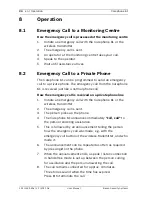
Page 34: ...ll How the emergency call is received on a private phone line 1 Initiate an emergency call with the Carephone 61 or the wireless transmitter 2 The emergency call is sent 3 The person picks up the phone 4 The Carephone 61 announces immediately call call to the person rendering assistance 5 This is followed by an announcement telling the person how the emergency call was made e g with the emergency ...

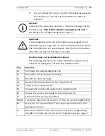
Page 35: ...g 0 or not extended by pressing 1 the call will not be properly processed The Carephone 61 will automatically dial the next call number when the existing call has been cancelled Key Function 0 Terminate and acknowledge the call 1 Extend the call by another 3 minutes 2 Repeat the alarm message 3 Speak with normal volume to the Carephone 61 4 Listen to the Carephone 61 5 Increase the volume and spea...

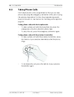
Page 36: ...not be set to 0 See Section 61 Incoming call recognition page 24 Taking phone calls with the Carephone 61 To take a phone call with the Carephone 61 press the emergency call button when the phone rings To stop the call press the emergency call button again Taking phone calls with the wireless transmitter To take a phone call with the wireless transmitter press the button of your wireless transmitt...

Page 37: ... the unit housing The surface of the housing can be damaged by abrasive products or products containing alcohol cleaning products containing alcohol or vinegar cleaning products for glass or plastics disinfectants except Incidur methylated spirits petroleum ether other aggressive agents If necessary remove the top cover of the Carephone 61 and clean the spaces in between the buttons For cleaning p...

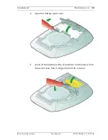
Page 38: ...ery The backup battery of the Carephone 61 has a limited operating life and should be replaced after 3 years To replace the battery 1 Disconnect the power cord from the unit 2 Disconnect the plug of the backup battery from the Carephone 3 Release the battery pack cover from the two clips by levering up with a screwdriver ...

Page 39: ...tenance en 39 Bosch Security Systems User Manual F 01U 239 30x V1 2011 06 4 Open the battery pack cover 5 Lever off the battery with a screwdriver and release it from the two braces Pull it out gently from its location ...

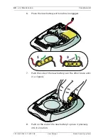
Page 40: ...1 2011 06 User Manual Bosch Security Systems 6 Place the new battery with one brace engaged 7 Push the side of the new battery over the other brace until it is clipped 8 Push on the end of the new battery to place it precisely into its location 1 2 ...

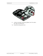
Page 41: ...arephone 61 Maintenance en 41 Bosch Security Systems User Manual F 01U 239 30x V1 2011 06 9 Connect the plug of the backup battery into the socket The plug can be reversed 10 Close the battery pack cover ...

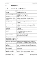
Page 42: ...rox 12 mA standby in battery operation Phone line connection PSTN Dial mode Tone dial Frequency 869 2125 MHz Receiver complies with class 1 as specified in EN 300220 1 V2 1 1 Protection class IP32 IP30 wall mounting IP67 wireless transmitter Environmental class Class 1 Max number of wireless transmitters or detectors 10 Emergency call protocols Multi protocol enabled RB2000 RB2000E ANT TTnew CPC B...

Page 43: ...or Kingston remote programming from monitoring centre separate programming tool protected by PIN Inputs and outputs 1 input and 1 relay output max 30 VDC Serial connection IP connection optional microSD port 3 5 mm jack external loudspeaker and microphone GSM gateway optional CE Directives CE R TTE 1999 5 EC LVD 73 23 EEC EMC 89 336 EEC Standards complied with EN50134 2 EN50134 3 EN301489 1 v1 8 1...

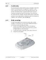
Page 44: ...ial alarm calls in Europe We Bosch Security Systems declare that the above mentioned products are manufactured in compliance with EU Directives 5 1999 EC LVD 73 23 EEC EMC 89 336 EEC A 3 Wall mounting For wall mounting you will need two screws with a shank diameter of less than 5 mm and a head diameter between 7 and 9 mm and two suitable wall plugs 1 Position the plugs and screws so that the dista...

Page 45: ...Carephone 61 en 45 Bosch Security Systems User Manual F 01U 239 30x V1 2011 06 This page is left intentionally blank ...

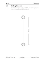
Page 46: ...6 en Carephone 61 F 01U 239 30x V1 2011 06 User Manual Bosch Security Systems A 4 Drilling template The drilling template can be used if this document is printed to the correct scale DIN A5 148 x 210 mm ...

Page 47: ...Carephone 61 en 47 Bosch Security Systems User Manual F 01U 239 30x V1 2011 06 This page is left intentionally blank ...

Page 48: ... on 0 26 Call back waiting time 0 9 minutes 0 off 0 28 Call forwarding 0 forwarding to another number 1 forwarding to a telephone 0 29 Hear speech impaired 0 off 1 on 0 30 Device number 1 2 4 8 32 Call progress tones audible 0 not audible 1 audible 0 33 Speak Listen command audible 0 not audible 1 audible 1 34 Personal voice recording max 6 seconds 41 to 45 refer to the user manual of the IP Modul...

Page 49: ...9 2 4 6 8 1 0 77 Pre alarm time 0 6 x 10 seconds 0 off 1 Code Target Setting 1 2 3 4 5 6 7 8 9 10 91 Wireless transmitter 1 81 81 92 Wireless transmitter 2 82 82 93 Wireless transmitter 3 83 83 94 Wireless transmitter 4 84 84 95 Wireless transmitter 5 85 85 96 Wireless transmitter 6 86 86 97 Wireless transmitter 7 87 87 98 Wireless transmitter 8 88 88 99 Wireless transmitter 9 89 89 90 Wireless tr...

Page 50: ...smitter registering 26 Emergency call button 8 H Hear speech impaired 20 I Incoming call recognition 23 Individual PIN code 25 IP Module 21 L Language 17 Language selection 17 Light signals 10 Loudspeaker volume 23 N Number of announcements when calling a telephone 22 P Personal voice recording 21 Pre alarm time 25 R Radio jamming 17 Radio transmission monitoring 19 Registering wireless transmitte...

Page 51: ......

Page 52: ...Bosch Security Systems Werner von Siemens Ring 10 85630 Grasbrunn Germany www boschsecurity com Bosch Security Systems 2011 ...

Reviews: