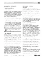
background image

6 720 220 048

Revised 05-12                                Subject to change without prior notice


25

CE Series

operating Pressures & Temperatures

oPeraTInG Pressures & TeMPeraTures

environmentally safe r-410a refrigerant

CE061

First

Step

CE061

Full

Capacity

CE071

First

Step

30°

40°

50°

60°

70°

80°

90°

100°

30°

40°

50°

60°

70°

80°

90°

100°

30°

40°

50°

60°

70°

80°

90°

100°

5.0

68-84

256-313

5-7

19-23

7.0

73-89

261-319

4-5

20-25

5.0

113-138

172-210

18-22

19-23

81-99

277-339

7-8

22-26

7.0

110-134

161-196

12-14

20-24

86-105

283-346

5-6

23-28

5.0

116-142

206-252

17-21

19-23

93-114

299-365

8-9

24-29

7.0

112-137

193-236

12-14

19-24

99-121

305-373

6-7

25-31

5.0

118-145

241-294

17-21

18-23

106-129

321-392

9-11

26-32

7.0

115-140

225-275

11-14

19-23

113-138

327-400

7-8

28-34

5.0

121-148

275-336

17-21

18-22

118-145

342-418

10-12

29-35

7.0

117-143

257-314

11-14

19-23

126-154

349-427

8-9

30-37

5.0

123-151

309-378

16-20

18-22

131-160

364-444

11-14

31-38

7.0

120-146

289-353

11-13

19-23

139-170

371-454

8-10

33-40

5.0

126-154

344-420

16-20

18-22

143-175

385-471

12-15

33-41

7.0

122-149

321-392

11-13

18-22

152-186

393-480

9-11

35-43

5.0

128-157

378-462

16-19

17-21

7.0

125-152

353-432

11-13

18-22

7.0

68-84

256-313

5-7

19-23

14.0

73-89

261-319

4-5

20-25

7.0

117-143

182-222

15-19

21-26

81-99

277-339

7-8

22-26

14.0

114-139

170-208

11-14

22-27

86-105

283-346

5-6

23-28

7.0

120-147

215-263

15-18

20-25

93-114

299-365

8-9

24-29

14.0

117-143

201-246

11-14

21-26

99-121

305-373

6-7

25-31

7.0

123-150

248-304

14-17

20-24

106-129

321-392

9-11

26-32

14.0

119-146

232-284

11-13

21-25

113-138

327-400

7-8

28-34

7.0

126-154

282-344

14-17

19-24

118-145

342-418

10-12

29-35

14.0

122-149

263-322

10-13

20-25

126-154

349-427

8-9

30-37

7.0

129-157

315-385

13-16

19-23

131-160

364-444

11-14

31-38

14.0

125-153

294-360

10-12

19-24

139-170

371-454

8-10

33-40

7.0

132-161

348-426

13-16

18-22

143-175

385-471

12-15

33-41

14.0

128-156

326-398

10-12

19-23

152-186

393-480

9-11

35-43

7.0

134-164

382-466

12-15

17-21

14.0

131-160

357-436

9-11

18-22

10.0

71-87

259-316

5-7

19-23

16.0

76-92

264-322

4-5

20-25

10.0

116-141

175-213

18-22

19-23

84-102

280-342

7-8

22-26

16.0

113-137

164-199

12-14

20-24

89-108

286-349

5-6

23-28

10.0

119-145

209-255

17-21

19-23

96-117

302-368

8-9

24-29

16.0

115-140

196-239

12-14

19-24

102-124

308-376

6-7

25-31

10.0

121-148

244-297

17-21

18-23

109-132

324-395

9-11

26-32

16.0

118-143

228-278

11-14

19-23

116-141

330-403

7-8

28-34

10.0

124-151

278-339

17-21

18-22

121-148

345-421

10-12

29-35

16.0

120-146

260-317

11-14

19-23

129-157

352-430

8-9

30-37

10.0

126-154

312-381

16-20

18-22

134-163

367-447

11-14

31-38

16.0

123-149

292-356

11-13

19-23

142-173

374-457

8-10

33-40

10.0

129-157

347-423

16-20

18-22

146-178

388-474

12-15

33-41

16.0

125-152

324-395

11-13

18-22

155-189

396-483

9-11

35-43

10.0

131-160

381-465

16-19

17-21

16.0

128-155

356-435

11-13

18-22

Suction

Pressure

PSIG

Water

Temp 

Drop °F

COOLING

HEATING (+)

Entering

Water

Temp. °F

Water

Flow

GPM

Water

Temp 

Rise °F

Air

Temp

Drop °F

Suction

Pressure

PSIG

Discharge

Pressure

PSIG

Air

Temp

Rise °F

Model

Discharge

Pressure

PSIG

This chart shows approximate temperatures and pressures for a unit in good repair. The values shown are meant as a guide only and 

should not be used to estimate system charge. This chart assumes rated air flow and 80º d.b./67º w.b. entering air temperature in 
cooling, 70º d.b. entering air temperature in heating. Heating data at entering fluid temperatures below 50º assumes the use of 
antifreeze. As a result of continuing research and development, specifications are subject to change without notice.

operating data

Summary of Contents for CE025

Page 1: ...Installation and Maintenance Manual CE Series 6 720 220 048 Revised 05 12 ...

Page 2: ... Copyright 2012 Bosch Inc All rights reserved ...

Page 3: ...wer Boiler Application 13 Earth Coupled Systems 14 System Checkout 14 Unit Start Up 14 Heat Recovery Package 15 Hot Gas Reheat 16 Maintenance 16 Well Water Application 17 Cooling Tower Boiler Application 18 Earth Coupled Application 19 Wiring Diagrams 20 Operating Pressures Temperatures 23 Unit Check Out 27 Trouble Shooting 28 Table of Contents Model Nomenclature SUPPLY AIR LOCATION T TOP VT ONLY ...

Page 4: ...should be left in its shipping carton and stored in a clean dry area Units must only be stored or moved in the normal upright position as indicated by the UP arrows on each carton at all times If unit stacking is required stack units as follows Vertical units less than 6 tons no more than two high Horizontal units less than 6 tons no more than three high Do not stack units larger than 6 tons SAFET...

Page 5: ...nection must be in conformance with local plumbing codes A trap must be installed in the condensate line to insure free condensate flow Heat Pumps are not internally trapped A vertical air vent is sometimes required to avoid air pockets See Figure 3 The length of the trap depends on the amount of positive or negative pressure on the drain pan A second trap must not be included Figure 3 MOUNTING VE...

Page 6: ...heat pump must have at least one 90 degree turn away from the space return air grille If air noise or excessive air flow are a problem the blower speed can be changed to a lower speed to reduce air flow Refer to ECM motor interface board section in this manual and Figure 7 PIPING Supply and return piping must be as large as the unit connections on the heat pump larger on long runs Never use flexib...

Page 7: ...with internal electric heat require two 2 separate power supplies one for the unit compressor and one for the electric heater elements blower motor and control circuit Refer to the ELECTRIC HEATER PACKAGE OPTION section and Figure 9 for wiring instructions minimum circuit ampacities and maximum fuse breaker sizing ECM INTERFACE BOARD THERMOSTAT CONNECTIONS Thermostat wiring is connected to the 10 ...

Page 8: ...settings for the CE Series Caution To the right of the thermostat connection block is a green LED labeled dehumidify Just above and to the right of the thermostat connection block are four sets of jumper pins labeled ADJ DELAY HEAT and COOL The ADJ set of pins are labeled NORM and TEST CE units will all be set on the NORM position from the factory however airflow can be increased or decreased by 1...

Page 9: ...ndensing water coil monitors refrigerant temperature between condensing water coil and thermal expansion valve If temperature drops below or remains at freeze limit trip for 30 seconds the controller will shut down the compressor and enter into a soft lockout condition The default freeze limit trip is 30 F however this can be changed to 15 F by cutting the R42 resistor located on top of DIP switch...

Page 10: ... input is active all the time if a freeze option is not selected the freeze terminals will need a jumper There are 2 configurable freeze points 30 F 15 F The unit will enter a soft lock out until the temperature climbs above the set point and the anti short cycle time delay has expired The freeze sensor will shut the compressor output down after 90 seconds of water flow loss and report a freeze co...

Page 11: ...1 LPC 1 FRZ TEMP LIM CON 0 INITIAL POWER UP T ASC OR RS SEC TIME 30 SEC TIME 120 SEC COUNT 2 Start Timer Start Timer CC Output On CC Output Off Blink Code On Status LED Report Alarm Fault Hard Lockout ALR Output On Pulse Blink Code On Status LED Soft Lockout Record Alarm Start Counter If Applicable Start Anti Short Cycle Start Random Start Up Lockout Can Be Set To 4 Via Dip Switch Power Switchs Se...

Page 12: ...ts Two power supplies are required when heater packages are utilized The power supply for the heater package located in the electric heater package control box provides power for the heater elements the blower motor and the control circuit for the unit The power supply for the unit provides power for the compressor This allows the electric heaters to continue to operate along with the blower motor...

Page 13: ...e In the cooling mode heat is rejected from the unit into the water loop A cooling tower provides Well Water Systems SEQUENCE OF OPERATION TWO STAGE UNITS Figure 13 Wiring Diagrams COOLING MODE Energizing the O terminal energizes the unit reversing valve in the cooling mode The fan motor starts when the G terminal is energized Note that the fan motor will take 30 seconds to ramp up to operating sp...

Page 14: ...UPLED SYSTEMS Figure 12 Closed loop and pond applications require specialized design knowledge No attempt at these installations should be made unless the dealer has received specialized training Utilizing Bosch s Ground Loop Pumping Package GLP makes the installation easy Anti freeze solutions are utilized when low evaporating conditions are expected to occur Refer to the GLP installation manuals...

Page 15: ...void the heat recovery package warranty along with the heat pump warranty TYPICAL CONNECTION PIPING Heat Recovery Package WATER TANK PREPARATION 1 Turn off electrical or fuel supply to the water heater 2 Attachgardenhosetowatertankdrainconnection andrunotherendofhoseoutdoorsortoanopen drain 3 Close cold water inlet valve to water heater tank 4 Drain tank by opening drain valve on the bottom of the...

Page 16: ...heat You should choose the means that best suits your specific application The Typical Wiring Diagram Figure 14 illustrates one possible control sequence Most heat pump compatible thermostats in conjunction with a humidistat are acceptable for use Note O output for reversing valve energized in cooling mode is required Combination thermostats humidistat are also available MAINTENANCE 1 Filterchange...

Page 17: ...E DISCONNECT UNIT 2 FLEX DUCT CONNECTION 3 LOW VOLTAGE CONTROL CONNECTION 4 LINE VOLTAGE CONNECTION 5 VIBRATION PAD 6 P T PORTS 7 HOSE KITS Optional 8 BALL VALVES 9 SOLENOID VALVE SLOW CLOSING 10 CONDENSATE DRAIN CONNECTION 11 PRESSURE TANK Optional 12 LINE VOLTAGE DISCONNECT ELECTRIC HEATER NOTE SEE FIGURE 3 FOR CONDENSATE DRAIN CONNECTION Well Water Application ...

Page 18: ...LINE VOLTAGE DISCONNECT UNIT 2 LOW VOLTAGE CONTROL CONNECTION 3 P T PLUGS Optional 4 HOSE KITS Optional 5 BALL VALVES 6 SUPPLY AND RETURN LINES OF CENTRAL SYSTEM 7 FLEX DUCT CONNECTION 8 HANGING BRACKETS ASSEMBLY 9 THREADED ROD 10 HANGING BRACKET ASSEMBLY ES048 and up 930 006 NOTE SEE FIGURE 3 FOR CONDENSATE DRAIN CONNECTION Cooling Tower Boiler Application ...

Page 19: ... 2 FLEX DUCT CONNECTION 3 LOW VOLTAGE CONTROL CONNECTION 4 LINE VOLTAGE CONNECTION UNIT 5 P T PORTS 6 VIBRATION PAD 7 CONDENSATE DRAIN 8 GROUND LOOP CONNECTION KIT 555 000 001 9 GROUND LOOP PUMPING PACKAGE GL001 1 or 002 1 10 POLYETHELENE WITH INSULATION 11 LINE VOLTAGE DISCONNECT ELECTRIC HEATER NOTE SEE FIGURE 3 FOR CONDENSATE DRAIN CONNECTION Earth Coupled Application ...

Page 20: ...20 Subject to change without prior notice Revised 05 12 6 720 220 048 CE Series Figure 13 Typical Wiring Diagrams Single Stage Two Step Single Phase ECM Motor Typical Wiring Diagram ...

Page 21: ...6 720 220 048 Revised 05 12 Subject to change without prior notice 21 CE Series Figure 13 Typical Wiring Diagrams Single Stage Two Step Single Phase ECM Motor 2 6 Ton Typical Wiring Diagram ...

Page 22: ...22 Subject to change without prior notice Revised 05 12 6 720 220 048 CE Series Figure 13 Typical Wiring Diagrams Single Stage Two Step Single Phase ECM Motor 2 6 Ton Typical wiring Diagram ...

Page 23: ...375 14 17 17 19 138 168 305 373 8 9 23 27 6 143 174 288 353 8 10 18 21 145 177 312 382 5 6 24 29 4 153 186 346 423 14 17 16 19 151 184 317 388 8 10 25 29 6 147 179 325 398 8 9 17 20 158 193 325 398 6 7 26 31 4 158 191 389 477 13 16 16 18 6 152 185 366 448 8 9 17 20 2 5 73 89 266 325 5 6 15 18 4 5 77 94 272 333 3 4 16 19 2 5 117 143 189 231 14 17 18 22 86 105 279 341 6 7 17 21 4 5 112 137 178 217 8...

Page 24: ...11 380 12 15 27 33 6 0 132 153 291 356 10 12 18 22 123 151 319 390 8 10 29 35 4 0 134 164 349 426 17 20 17 20 128 157 324 396 13 16 29 36 6 0 129 158 328 401 9 12 18 22 135 165 332 406 9 11 31 38 4 0 139 170 392 480 16 20 16 20 6 0 133 163 369 451 9 11 17 21 6 0 71 87 277 339 6 7 15 19 12 0 75 92 284 347 4 5 16 20 6 0 118 144 194 237 21 25 19 23 84 102 291 356 7 9 18 22 12 0 113 138 182 223 12 14 ...

Page 25: ...29 157 315 385 13 16 19 23 131 160 364 444 11 14 31 38 14 0 125 153 294 360 10 12 19 24 139 170 371 454 8 10 33 40 7 0 132 161 348 426 13 16 18 22 143 175 385 471 12 15 33 41 14 0 128 156 326 398 10 12 19 23 152 186 393 480 9 11 35 43 7 0 134 164 382 466 12 15 17 21 14 0 131 160 357 436 9 11 18 22 10 0 71 87 259 316 5 7 19 23 16 0 76 92 264 322 4 5 20 25 10 0 116 141 175 213 18 22 19 23 84 102 280...

Page 26: ...13 16 18 22 146 178 388 474 12 15 33 41 16 0 131 159 329 401 10 12 19 23 155 189 396 483 9 11 35 43 10 0 137 167 385 469 12 15 17 21 16 0 134 163 360 439 9 11 18 22 Suction Pressure PSIG Water Temp Drop F COOLING HEATING Entering Water Temp F Water Flow GPM Water Temp Drop F Air Temp Drop F Suction Pressure PSIG Discharge Pressure PSIG Air Temp Rise F Model Discharge Pressure PSIG This chart shows...

Page 27: ...__ ______________ Fluid Flow gpm ______________________________ ______________________________ Compressor Volts Amps _______________ ______________ _______________ ______________ Blower Motor Volts Amps _______________ ______________ _______________ ______________ Source Fluid Type _______________________________ ______________________________ Fluid Flow gpm ______________________________ ________...

Page 28: ... grounded Internal winding grounded to the compressor shell Replace compressor If compressor burnout install suction filter dryer Compressor windings Open After compressor has cooled check continuity of the compressor windings If the windings are open replace the compressor Unit off on high pressure control Discharge pressure too high In COOLING mode Lack of or inadequate water flow Entering water...

Page 29: ...ng bypass of refrigerant from discharge of suction side of compressor Replace reversing valve Operating pressures Compare unit operation pressures to the pressure temperature chart for the unit TXV Check TXV for possible restriction or defect Replace if necessary Moisture noncondensables The refrigerant system may be contaminated with moisture or noncondensables Reclaim refrigerant replace filter ...

Page 30: ...30 Subject to change without prior notice Revised 05 12 6 720 220 048 CE Series Notes ...

Page 31: ...6 720 220 048 Revised 05 12 Subject to change without prior notice 31 CE Series Notes ...

Page 32: ...601 N W 65th Court Ft Lauderdale FL 33309 Phone 954 776 5471 Fax 954 776 5529 www boschtaxcredit com www bosch climate us Revised 05 12 ...

Reviews: