


1 4 |
Bosch Climate 5000 AA Series Inverter Multi Split-Type Air Conditioner/ Heat Pump
Installation Manual
01.2017
|
Bosch Thermotechnology Corp.
Data subject to change
CAUTION:
Ensure to wrap insulation around the piping. Direct contact
with the bare piping may result in burns or frostbite.
NOTICE:
Make sure the pipe is properly connected. Over tightening
may damage the bell mouth and under tightening may lead to
leakage.
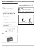
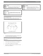
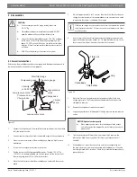
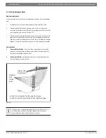
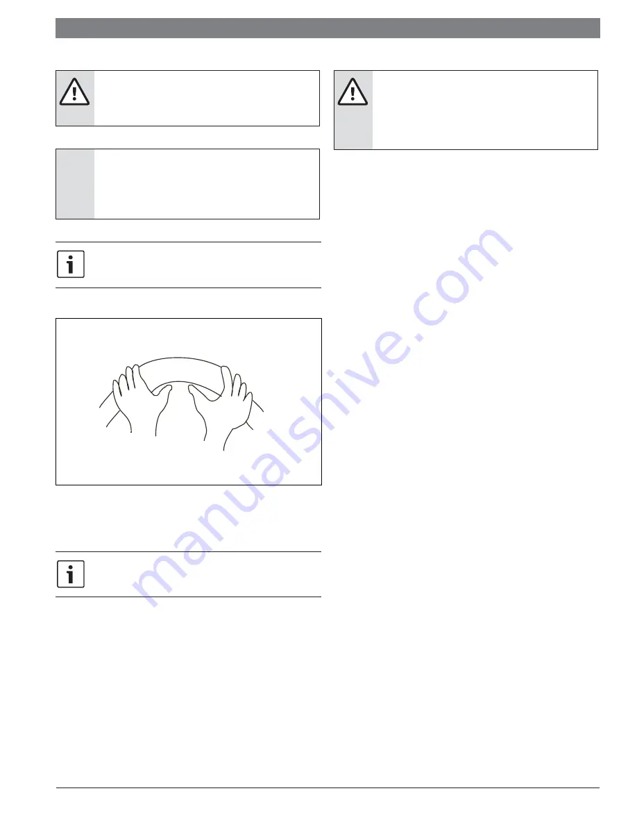
MINIMUM BEND RADIUS
Carefully bend the tubing in the middle according to the diagram below.
DO NOT bend the tubing more than 90° or more than 3 times.
Bend the pipe with thumb
min-radius 10cm (3.9”)
Figure 18
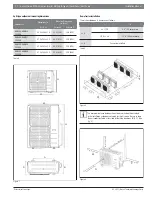
6.
After connecting the copper pipes to the indoor unit, wrap the power cable,
signal cable and the piping together with binding tape.
DO NOT intertwine signal cable with other wires. While bundling these
items together, do not intertwine or cross the signal cable with any other
wiring.
7.
Thread this pipeline through the wall and connect it to the outdoor unit.
8.
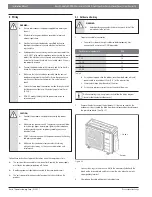
Insulate all the piping, including the valves of the outdoor unit.
9.
Open the stop valves of the outdoor unit to start the flow of the refrigerant
between the indoor and outdoor unit.
CAUTION:
Check to make sure there is no refrigerant leak after
completing the installation work. If there is a refrigerant leak,
ventilate the area immediately and evacuate the system (refer
to the Air Evacuation section of this manual).


