A D00 A49 029
|
2017-06-09
Robert Bosch Engineering and Business Solutions Private Limited
4.7
Splash guard and CO
2
sensor
assembly
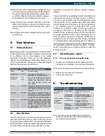
To assemble splash guard and CO
2
sensor on the unit:
i
Splash guard has to be assembled when the unit is
mounted on wall. This is needed as space is required
to fix the screw through the mounting bracket.
i
Avoid installing any other equipment around sensors
(CO2 & UV sensors).
1.
Assemble the CO
2
sensor, and plastic mounting flange
with self tapping screw.
2.
Fix it to the Splash guard with the provided M5 screws.
3.
Fix the Splash guard to the bottom mounting bracket
with help of provided screws.
!
Take care not to apply excess load while installing
the splash guard, as the unit is not a load carrying
component and can cause damage.
!
Do not rest the unit on splash guard.
i
While assembling handle, CO
2
sensor with care and
avoid installing any other equipment around the
sensor.
Fig. 8:
Splash guard with CO
2
sensor
4.8
AC DC connection
To connect AC or DC cable to the unit:
1.
When the unit is assembled either on pole or wall,
check that the unit is in perfect condition and
without any damage.
2.
Fix the AC or DC cable harness as per the label
indicated on the unit.
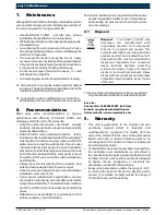
Fig. 9:
Notch for mating connector
3.
Insert the mating connector keeping notch as
reference.
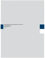
i
Mating connector should be in unlock position and
inserted completely as shown in the figure below.
Fig. 10:
Mating connector insertion
4.
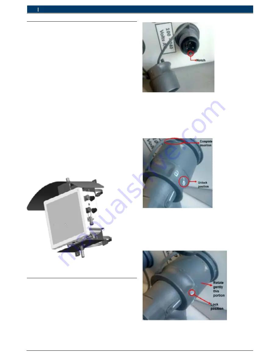
Lock the mating connector.
i
Carefully insert the connector into the notch with
a gentle push and it should not give crunch sound.
Smooth lock should happen.
Fig. 11:
Mating connector locked
en
14 | Installation


