background image

6721835318  (2021/09) GB

Installation Manual 

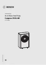
Air to Water Heat Pump

Compress 7001i AW

5-17 OR-S/T

Summary of Contents for Compress 7001i AW

Page 1: ...6721835318 2021 09 GB Installation Manual Air to Water Heat Pump Compress 7001i AW 5 17 OR S T ...

Page 2: ...rt 10 5 1 1 Transport fitting 10 5 2 Unpacking 10 5 3 Checklist 10 5 4 Mounting method 10 5 4 1 Assembly of the heat pump 10 5 5 Connection 11 5 5 1 Pipework connections general 11 5 5 2 Water connecting pipe 13 5 5 3 Connection of heat pump to the indoor unit 13 5 5 4 Electrical connection 13 5 6 Installing side panels and cover 15 6 Maintenance 17 7 Installation of accessories 17 7 1 Heating cab...

Page 3: ...rical work may only be performed by authorised electrical installers Before commencing work Disconnect mains voltage on all poles and ensure it cannot reconnect Check to ensure that the power is disconnected Also check the connection diagram for other parts of the system H Handover to the user When handing over instruct the user how to operate the heating system and inform the user about its opera...

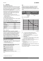
Page 4: ...iciency Follow the guidance of BS7593 for treatment of water in domestic hot water heating systems1 Do not use anti freeze glycol products Suitable water treatment products inhibitors cleaners can be obtained from the following manufacturers Table 3 If the limits for water hardness stated in table 2 are exceeded the performance of the heat pump will deteriorate over time If this performance degrad...

Page 5: ...n of conformity Thedesignandoperatingcharacteristicsofthisproductcomplywiththe European and national requirements The CE marking declares that the product complies with all the applicable EU legislation which is stipulated by attaching this marking The complete text of the Declaration of Conformity is available on the Internet worcester bosch co uk 3 4 Type plate The data plate is located on the r...

Page 6: ...R0 3 Four way valve 4 Pressure switch pressure sensor 5 compressor 6 Inverter Description applies for all sizes 3 6 Dimensions 3 6 1 Dimension of heat pump models 5 OR S 7 OR S 9 OR S Fig 4 Dimensions and connections of heat pump models 5 OR S 9 OR S Fig 5 Dimensionsofheatpumpmodels5OR S 9OR S viewfromtop 1 2 3 4 6 5 352 99 76 405 1380 836 440 583 478 510 ø10 5 930 ...

Page 7: ...es during setup Fig 8 Clearances during setup Theclearancecanbereducedononeside Thismayhoweverlead to a higher noise level A Installation clearances of heat pump B Installation clearances of heat pump with sound insulation accessory 380 132 72 401 1695 976 545 656 548 680 ø10 5 1122 H 努 1200 努 2000 努 700 努 2000 努 2000 努 800 努 500 努 2000 努 700 努 2000 努 2000 H 努 1200 H 努 1200 H 努 1200 努 2000 努 400 努...

Page 8: ...ig 9 Avoid placement in locations surrounded by walls With a free standing installation not near the building or on a roof Donotinstalltheheatpumpsothattheairintakesidefacesdirectly south to avoid the effects of the sun on the air temperature sensor Protect the air intake side by a wall or similar object to avoid having strong winds blowing straight through the heat pump Fig 10 Free standing heat ...

Page 9: ...adiators without mixer and buffer cylinder If the system only contains a few radiators the auxiliary heater may be activated in the final phase of the defrosting process The radiator thermostats must be opened fully 1 radiator with 500 W rating required for heat pump 5 OR S 9 OR S 4 radiators each with roughly 500 W rating required for heat pump 13 OR S 17 OR T Toensuremaximumenergysavingsandavoid...

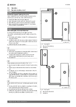
Page 10: ...d accessories Check that all package contents are present 5 3 Checklist Each installation is different The checklist below provides a general description of the installation process 1 Install and fix the heat pump on a solid surface 2 Install condensate tube of the heat pump and possibly the pipe trace heating 3 Connect heat pump to the indoor unit 4 Connect CAN BUS cable to heat pump and indoor u...

Page 11: ...at conductingpipeworkmustbeprovidedwithsuitablethermal insulation according to applicable regulations In cooling mode all connections and lines must be insulated according to applicable standards to prevent condensation Seal wall outlet Dimension pipes according to instructions Tab 6 8 To minimise pressure drops avoid joints in the heat transfer medium line Use PEX pipes for all pipework between t...

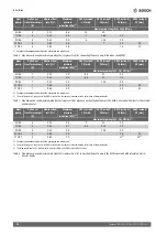
Page 12: ...r medium K Nominal flow rate l s Maximum pressure reduction kPa 1 1 For pipes and components between the heat pump and indoor unit AX20 inside Ø 15 mm AX25 inside Ø 18 mm AX32 inside Ø 26 mm AX40 inside Ø 33 mm Maximum pipe length A 16 PEX m 2 2 The installation of a 3 way valve in the DHW circuit of the system was factored into the calculation of the pipe lengths 5 OR S 7 0 32 50 8 5 21 30 7 OR S...

Page 13: ...um inlet of the heat pump 2 Fig 18 Tighten connections of the heat transfer medium pipes with a starting torque of 120 Nm Direct the force downwards Fig 18 to avoid lateral loading of the condenser If the connection does not seal properly the joint can be tightened with a starting torque of up to 150 Nm If the connection is still not tight this indicates that the gasket or connected pipe is damage...

Page 14: ... length is 30 m The connection is made with four wires as the 12 V supply is also connected Onthecircuitboardthereisamarkingfor12 VandCAN BUS connections Switch Term is used to indicate the start and end of a CAN BUS loop The heat pump I O module card should be terminated Fig 19 Termination CAN BUS Connecting the heat pump A CAN BUS signal cable with the minimum dimensions 4 x 0 75 mm2 and a maxim...

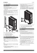
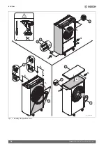
Page 15: ...llation 15 Compress 7001i AW 6721835318 2021 09 5 6 Installing side panels and cover Fig 21 Installing side panels and cover 1x 1 1x 2 1x 3 1x 4 1x 5 1 2 1 1 2 3 2 3 0010020097 002 4x 7 4x 8 4x 9 4x 10 2x 6 ...

Page 16: ...Installation Compress 7001i AW 6721835318 2021 09 16 Fig 22 Installing side panels and cover 3 9 9 8 5 4 4 4 6 8 9 5 7 10 0010020098 003 10 6 6 7 ...

Page 17: ...ays protect the expansion valve from impacts and shock NOTICE Deformation due to heat If the temperature is too high the insulation material EPP in the heat pump deforms Remove as much insulation EPP as possible before carrying out soldering work When carrying out soldering work in the heat pump protect the insulation material with heat resistant materials or a moist cloth Work on the refrigerant ...

Page 18: ...Installation of accessories Compress 7001i AW 6721835318 2021 09 18 3 4 A A 5 C A 6 A 7 C A A N N 1 1 8 A 9 C C B B 10 ...

Page 19: ...ng or disposal Old electrical and electronic appliances This symbol means that the product must not be disposed of with other waste and instead must be taken to the waste collection points for treatment collection recycling and disposal The symbol is valid in countries where waste electrical and electronic equipment regulations apply e g European Directive 2012 19 EC on old electronic and electric...

Page 20: ...4 IP X4 Fuse rating for supplying the heat pump directly via the building connection2 2 Fuse class gL C A 10 16 16 25 Maximum power consumption KW 2 9 3 2 3 6 7 2 Performance factor cos phi with maximum output 0 97 0 97 0 96 0 97 Rated power input of compressor with A 7 W35 rated output KW 1 67 2 13 1 95 4 36 Performance factor cos phi with A7 W35 0 97 0 97 0 96 0 97 Heat pump soft start Yes Yes Y...

Page 21: ...an 3 m from the wall dB A 50 44 40 38 36 34 32 30 28 27 26 3 m2 2 Heat pump closer than 3 m to the wall dB A 53 47 43 41 39 37 35 33 31 30 29 Night 3 m1 dB A 43 37 33 31 29 27 25 23 21 20 19 3 m2 dB A 46 40 36 34 32 30 28 26 24 23 22 Detailed sound pressure level max 7 OR S Clearance m 1 2 3 4 5 6 8 10 12 14 16 Day 3 m1 1 Heat pump more than 3 m from the wall dB A 55 49 45 43 41 39 37 35 33 32 31 ...

Page 22: ...wall dB A 54 48 44 42 40 38 36 34 32 31 30 Night 3 m1 dB A 47 41 37 35 33 31 29 27 25 24 23 3 m2 dB A 50 44 40 38 36 34 32 30 28 27 26 Detailed sound pressure level max 13 OR S Clearance m 1 2 3 4 5 6 8 10 12 14 16 Day 3 m1 1 Heat pump more than 3 m from the wall dB A 56 50 46 44 42 40 38 36 34 33 32 3 m2 2 Heat pump closer than 3 m to the wall dB A 59 53 49 47 45 43 41 39 37 36 35 Night 3 m1 dB A...

Page 23: ...g for supplying the heat pump directly via the building connection2 2 Fuse class gL C A 13 13 Maximum power consumption KW 7 2 7 2 Performance factor cos phi with maximum output 0 97 0 97 Rated power input of compressor with A 7 W35 rated output KW 3 92 5 11 Performance factor cos phi with A7 W35 0 97 0 97 Heat pump soft start Yes Yes Soft start type Inverter Inverter Max number of compressor star...

Page 24: ...k accessories Clearance m 1 2 3 4 5 6 8 10 12 14 16 Day 3 m1 1 Heat pump more than 3 m from the wall dB A 53 47 43 41 39 37 35 33 31 30 29 3 m2 2 Heat pump closer than 3 m to the wall dB A 56 50 46 44 42 40 38 36 34 33 32 Night 3 m1 dB A 48 42 38 36 34 32 30 28 26 25 24 3 m2 dB A 51 45 41 39 37 35 33 31 29 28 27 Detailed sound pressure level max 17 OR T Clearance m 1 2 3 4 5 6 8 10 12 14 16 Day 3 ...

Page 25: ...rox 20 C or 35 C The indoor unit or an external heat source then take over the heating and DHW heating The heat pump restarts if the outdoor temperature exceeds roughly 17 C or falls below 32 C In cooling mode the heat pump switches off at roughly 45 C and restarts at roughly 42 C Fig 23 Heat pump without auxiliary heater 1 Maximum flow temperature T0 2 Outdoor temperature T1 Unit 13 OR S 17 OR T ...

Page 26: ...sensor heat transfer medium outlet TL2 Temperature sensor air intake TR1 Temperature sensor compressor TR3 Temperaturesensor condenserreturn liquid heatingmode TR4 Temperature sensor evaporator return liquid cooling mode TR5 Temperature sensor suction gas TR6 Temperature sensor hot gas VR0 Electronic expansion valve 2 condenser VR1 Electronic expansion valve 2 evaporator VR4 Four way valve M M M T...

Page 27: ...ating current three phase current Fig 25 Wiring diagram for transformer alternating current three phase current ER1 Compressor MR1 High pressure switch V1 EMC filter only for 13kW 1N A Inverter B Mains voltage 230V 1N 5 13kW C Mains voltage 400V 3N 13 17kW 1 Power supply of I O module 2 MOD BUS to I O module B 2 C A 1 2 A 1 ...

Page 28: ...R3 Temperature sensor at condenser return TR5 Temperature sensor suction gas TR6 Temperature sensor hot gas VR0 Electronic expansion valve 1 VR1 Electronic expansion valve 2 EA0 Heater for drip pan EA1 Heating cable accessory F50 Fuse 6 3A PL3 Fan SSM Motor protection in the fan VR4 Four way valve A I O module B P1 heat pump 5 OR S 1N P2 heat pump 7 OR S 1N P3 heat pump 9 OR S 1N P4 heat pump 13 O...

Page 29: ...l charge size of the refrigerant in the table information on refrigerant of the operating instructions C r C r C r 40 154300 5 11900 50 1696 35 111700 10 9330 55 1405 30 81700 15 7370 60 1170 25 60400 20 5870 65 980 20 45100 25 4700 70 824 15 33950 30 3790 75 696 10 25800 35 3070 80 590 5 19770 40 2510 85 503 0 15280 45 2055 90 430 C C C C 20 96358 15 15699 50 3605 85 1070 15 72510 20 12488 55 298...

Page 30: ......

Page 31: ......

Page 32: ... Cotswold Way Warndon Worcester WR4 9SW United Kingdom Tel 0330 123 9559 worcester bosch co uk 0330 123 3366 TECHNICAL SUPPORT RENEWABLE SUPPORT 0330 123 9229 CONTROLS AND CONNECTIVITY TEAM 0330 123 3641 0330 123 9339 0330 123 9779 0330 123 9119 0330 123 0166 0330 123 9669 ...

Reviews: