From
Our Reference
Tel
XC-DA/ECR3-Bp
Daniel Radics
+36 1 879-6276
Issue
1.0
Topic
CR5CBCC User Manual
Budapest
10 June 2021
Page 14 of 17
Report
CR5CBCC_User_manual.docx
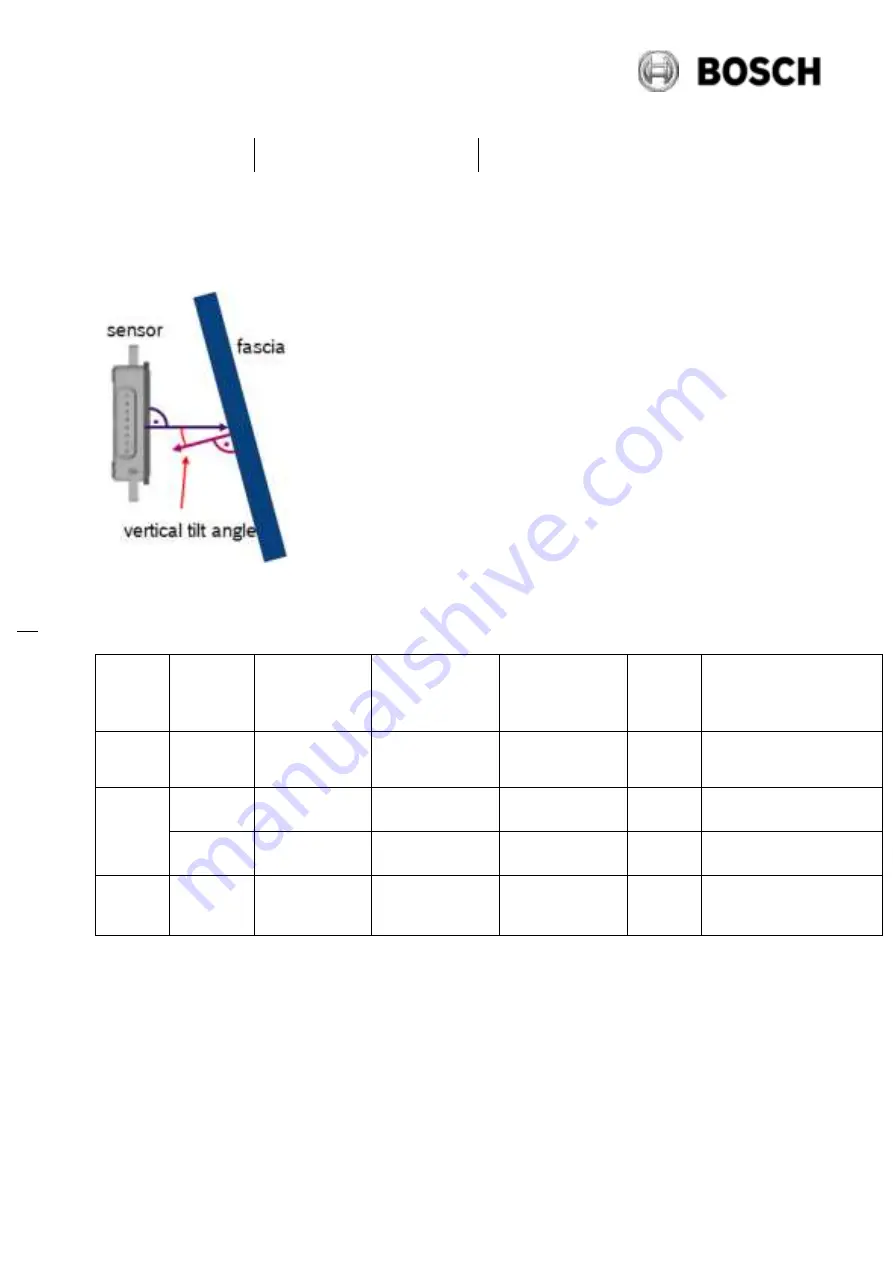
Figure 6: vertical tilt angle of fascia to sensor normal
Vertical tilt angle t.b.c:
Vertical
tilt
Reflectio
n
coefficien
t
Max.
tolerance
thickness
Permittivity εr
Tolerance
Permittivity εr
tanδ
Type of fascia
>2°
<-14 dB
±0.1 mm
single value
±0.05
<0.03
unpainted (black)
bumper
>6°
<-10 dB
±0.2 mm
single value
±0.05
<0.03
unpainted (black)
bumper
<-6 dB
-
range from 2.5
to 3.2
±0.05
<0.02
painted bumper
>8°
>-6 dB
-
range from 2.5
to 3.2
±0.05
>0.02
painted bumper
Table: minimum vertical tilt angle of fascia to sensor normal
The values provided in the previous table are derived from evaluation of flat plates with constant
thickness and homogeneous material. Deviations from this situation may cause a change in
classification and the vertical tilt angle of fascia has to be increased.


