D1256/D1257
Installation
D1256/D1257 Installation Instructions
© 2004 Bosch Security Systems
Page 15
74-06925-000-H
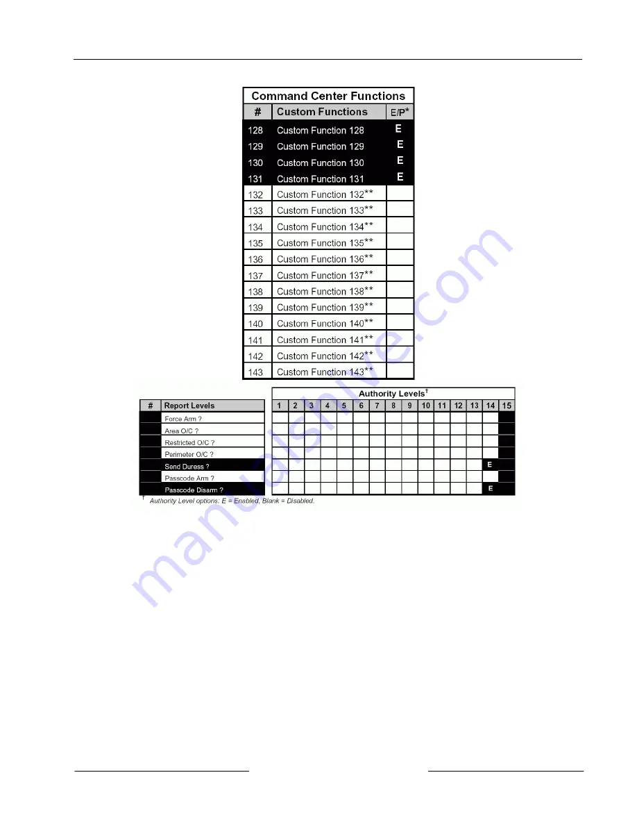
Figure 7 (cont’d): Example 6 – User Interface for D7212, D7212G, D7412, D7412G, D9112, D9412, D9412G
and D9124 (using the D9112LTB-EX or D9412GLTB)
4.3.6.1 Command Center Functions
The following command center function must be turned on to enable the [DETECTOR RESET] key.
•
#27 Reset Sensors
It is suggested that the items below be included in the menu.
•
#9 View Event Memory
•
#10 View Point Status
•
#12 Fire Test
•
#21 View Log
•
#29 Remote Program
•
#32 Display Rev


