D600 Series
|
Installation Guide | 7.0 Assigning a device address
Bosch Security Systems | 8/04 | 44677G
5
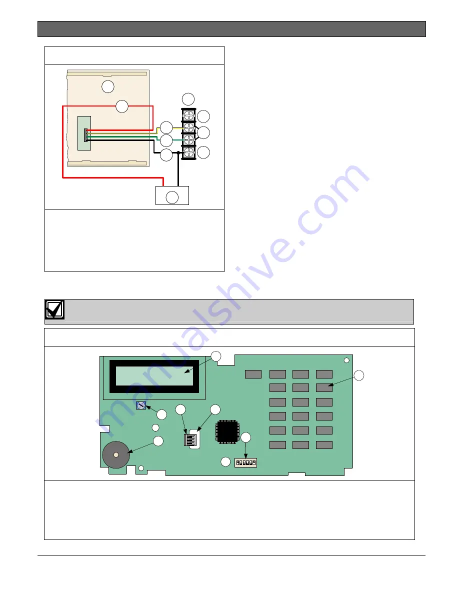
Figure 6: External power for keypads
(+)
(-)
1
2
3
5
4
6
7
8
9
10
1 - Back of keypad
2 - Control panel
terminals
3 - AUX Power (+)
4 - Data
5 - Common
6 - External 12 VDC
power supply
7 - Red
8 - Yellow
9 - Green
10 - Black
7.0 Assigning a device address
Each time you change the address switches, you must cycle the power to the keypad (turn the power
off and then on) for the address change to take effect.
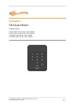
Figure 7: Inside view of keypad
O
N
1
2
3
4
5
6
1
2
3
4
5
6
7
1 - LCD display (D623/D623W/D623B),
LED display (D621/D621W/D621B), or
vacuum florescent display
(D625/D625WD625B)
2 - Keypad
3 - Wire opening
4 - Data wire connector
5 - 6-position DIP switch
6 - Backlight brightness potentiometer
(D623, D623W and D623B only)
7 - Speaker


