88
en | Analog and Frequency Inputs
Display Unit DDU 7
04.02.2019 | V 02 |
Manual
Bosch Motorsport
1.
Click ‘Measurement Sources’ in the Toolbox.
2.
Expand the list of ‘I/O Channels’ by clicking on ‘+’ in the DDU 7 Project Tree.
3.
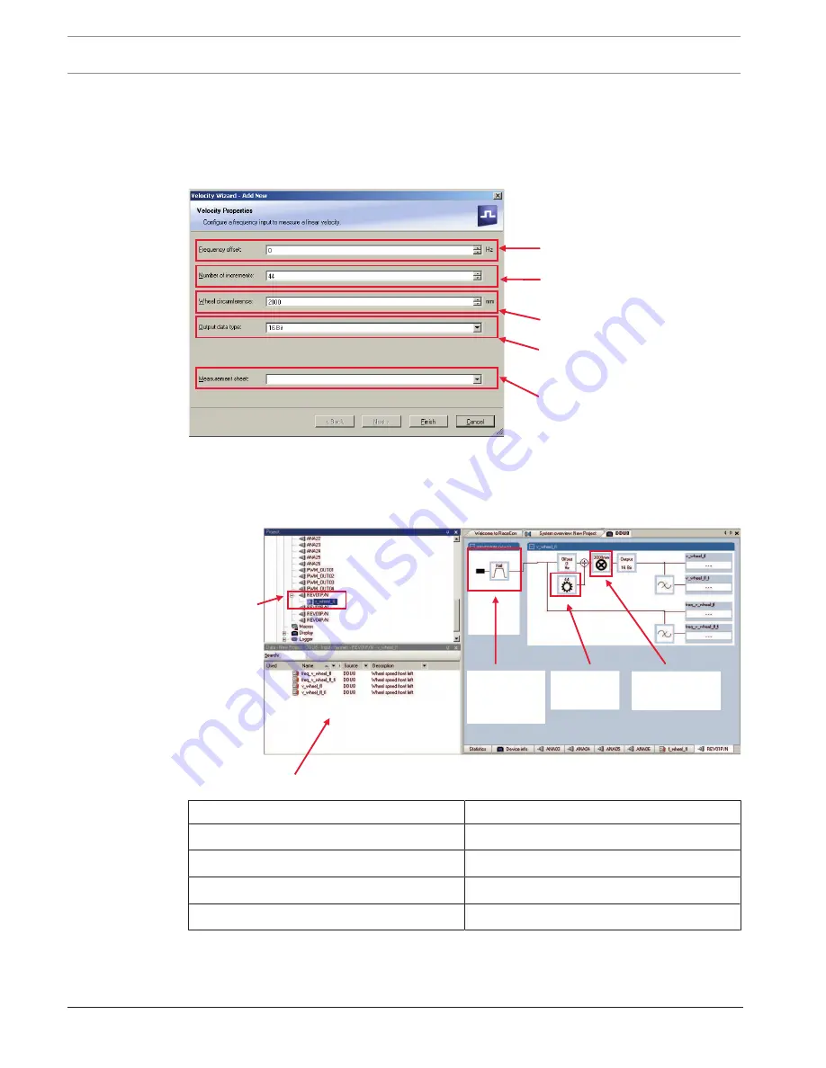
Drag the ‘Velocity’ digital signal source from the Toolbox and drop it on the desired ‘REV’
input channel in the DDU 7 Project Tree.
4.
The ‘Velocity Wizard’ opens.
Choose data type of the
measurement variable
Circumference of wheel for
speed calculation
Special functionality for sensors
with frequency offset (e.g.
Correvit) Set to ‘0’ for wheelspeed
measurement
Number of teeth on the pulse
wheel
Enter name to automatically
create a new measurement
sheet
5.
Click ‘Finish’ when done.
6.
Enter channel name and description.
7.
Click ‘OK’ when done.
The channel is inserted into the DDU 7 Project Tree.
Input pin
has hall
interface
Number of
teeth
Wheel
circumference
Channel is
linked to
REV01
Available measurements for channel:
Measurement label
Function
raw_name
mV value of sensor
raw_name_fi
filtered mV value of sensor
name
physical value of sensor
name_fi
filtered physical value
Summary of Contents for DDU 7
Page 1: ...Display Unit DDU 7 Manual V 02 2 4 2019 ...
Page 2: ......
Page 139: ...Display Unit DDU 7 Firmware en 139 Bosch Motorsport Manual 04 02 2019 V 02 ...
Page 155: ......


