


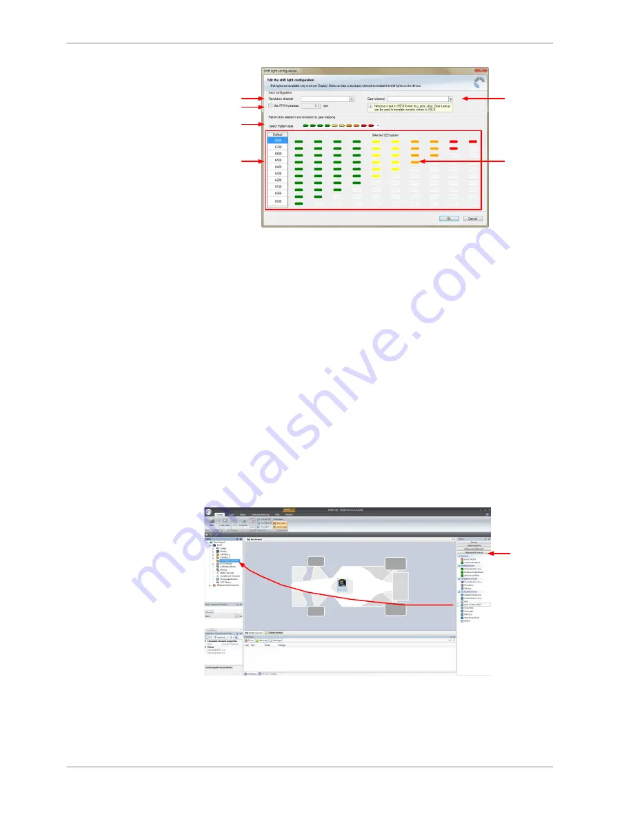
a)
b)
c)
d)
e)
f)
a) Choose the measement channel for 'Revolution'. Revolution must have 1/min quantization.
b) Enter the limit value when the RPM hysteresis function is active. The RPM hysteresis function avoids
the high-frequent switchover of the measurement channel value.
c) Choose a predefined Pattern style.
d) Define the gear (must be ASCII quantization). Only if gear channel is used.
e) Choose the measurement channel for 'Gear'. Gear must have an ASCII quantization (1st gear='1' = 49,
2nd gear='2' = 50, ...). (ASCII quantization is standard for the 'gear' channel of Bosch ECUs.
If you get the gear information of a different control unit as the Bosch ECU (e.g. a gearbox control unit),
use the Gear Lookup Table to translate numeric values to ASCII format.
For more information see chapter "Converting a gear channel to ASCII representation.)
4. Click ‘OK’ when done.
The configuration is displayed in the DDU 8 LED Configuration window.
Converting a gear channel to ASCII representation
If you get the gear information of a different control unit as the Bosch ECU (e.g. a
gearbox control unit), use the Gear Lookup Table to translate numeric values to
ASCII format.
1. Click on the Measurement Sources button in the Toolbox.
2. Drag the ‘Gear Lookup Table’ symbol and drop it in the ‘Computed Channels’
folder.
Drag + Drop
Measurement
sources
The Gear Lookup Table Wizard appears.
Gear Lookup Table Wizard
1. Set up the settings as shown in the screenshot.
8.3.2
8 | Display Configuration
34 / 136
DDU S2 PLUS Manual
Bosch Motorsport


