background image

11

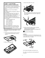
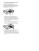
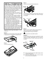
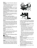
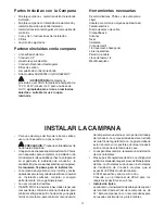
9. Choose Venting Option

The hood can be set to vent outside or to
recirculate air back into the kitchen.
The plastic vent lever is located near the center
of the hood opening.

To vent to the outside, 

make sure the plastic

vent lever is in the 

HORIZONTAL 

position (flat

against the metal top of the hood).

To recirculate air into the kitchen, 

make sure

the plastic vent lever is in the 

VERTICAL

position (flat against the plastic blower housing).
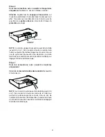
NOTE: 

In order to change the vent lever

position, you will need to pull the lever out
slightly to clear the plastic tabs.

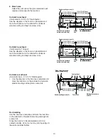
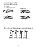
10.For recessed bottom cabinet only

If the cabinets have front, side or back trim,
make 2 wood shims the width of the trim and
attach them to the cabinet bottom recess on
both sides. See previous page for marking
locations.

11.

Cut holes at marked locations for duct and
electrical wiring. For the vertical duct, cut out 3/
4” extra toward the front of the cabinet so you
can move the duct freely when installing the
hood.
It may also ease installation by cutting the hole
10 1/2” instead of 10”.
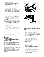
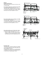
12.

Drive a mounting screw (from the hardware
packet) partway into each center of the narrow
neck of the keyhole slots marked on the cabinet
bottom.

13.

Fix the wiring conduit to the hood.

14.

Slide the hood back against the wall. Tighten
the mounting screws. Be sure the screw heads
are in the narrow neck of the keyhole slot.
Connect Ductwork to hood.

15.WIRING THE HOOD

 WARNING

Electrical Shock Hazard
Warning: Turn off power at the service panel
before wiring this unit.
120 VAC, 15 or 20 Amp circuit required.

ELECTRICAL GROUNDING INSTRUCTIONS

THIS APPLIANCE IS FITTED WITH AN
ELECTRICAL JUNCTION BOX WITH 3 WIRES,
ONE OF WHICH (GREEN/YELLOW) SERVES TO
GROUND THE APPLIANCE.  TO PROTECT YOU
AGAINST ELECTRIC SHOCK, THE GREEN AND
YELLOW WIRE MUST BE CONNECTED TO THE
GROUNDING WIRE IN YOUR
HOME ELECTRICAL SYSTEM, AND IT MUST
UNDER NO CIRCUMSTANCES BE CUT OR
REMOVED.

Set for

outside venting

Set for

recirculating

Stop tab

Stop tab

Hood shown Lying upside down

Failure to do so can result in death or electrical
shock.

If not already done,  install 1/2” conduit
connector in j-box.

Run black (live), white (neutral), and green
(earth) wires (#14 AWG) according to the
National Electrical Code or CSA Standards and
local codes and ordinances in 1/2” conduit from
power supply to j-box.

Connect black, white, and green wires from
power supply to black (live), white (neutral), and
green/yellow (earth) wires in j-box respectively.

These connections should be done always
making reference to the electrical diagram
found inside the hood.

Close j-box cover.

Final installation steps

16.

Replace filters as described in the Care & Use
section of this manual.
Models DUH30252UC and DUH36252UCOnly:
Install the lamps on proper housings.

Note:

 Lamps are  not supplied, use ONLY 120

Volt, 50 Watt (maximum)  50° halogen light
made for a GU10 base, 

suitable for use in

open luminarie

.

Turn power on at service panel.  Check
operation of the hood.

Wood shims

Summary of Contents for DUH

Page 1: ...Bosch ventilation installation manual DUH Models ...

Page 2: ...TALLER Please leave these Instructions with this unit for the owner OWNER Please retain these instructions for future reference Safety Warning Turn off power circuit at service panel and lock out panel before wiring this appliance Requirement 120 V AC 60 Hz 15 or 20 A Branch Circuit APPROVED FOR RESIDENTIAL APPLIANCES FOR RESIDENTIAL USE ONLY READ AND SAVE THESE INSTRUCTIONS ...

Page 3: ...nd Air Conditioning Engineers ASHRAE and the local code authorities E When cutting or drilling into wall or ceiling do not damage electrical wiring and other hidden utilities F Ducted systems must always be vented to the outdoors WARNING CAUTION FOR GENERAL VENTILATING USE ONLY DO NOT USE TO EXHAUST HAZARDOUS OR EXPLOSIVE MATERIALS OR VAPORS CAUTION To reduce risk of fire and to properly exhaust a...

Page 4: ...NT Save Installation Instructions for electrical inspector s use The range hood must be connected with copper wire only The range hood should be connected directly to the fused disconnect or circuit breaker box through metal electrical conduit Wire sizes must conform to the requirements of the National Electrical Code ANSI NFPA 70 latest edition or CSA Standards C22 1 94 Canadian Electrical Code P...

Page 5: ...idering cut to be done on wall and or on cabinet installation of ducts conduit and electrical connections to the mains 16 installation steps are required The hood is fitted with Screws and Drywall Anchors suitable for most surfaces consult a Qualified Installer check if they perfectly fit with your cabinet wall Do not use flex ducting COLD WEATHER installations should have an additional backdraft ...

Page 6: ... or can be installed in a recirculating ductless version Vertical discharge Use a rectangular duct 3 1 4 x 10 or use a round 7 duct Horizontal discharge Use a rectangular duct 3 1 4 x 10 Recirculating non vented ductless Examples of possible ducting Horizontal discharge Vertical discharge Recirculating ...

Page 7: ...7 TOTAL of both columns ...

Page 8: ... duct fitting exists Limit use to short lengths and do not crush when making corners After having choosen the vent option proceed as follows 2 Remove the round transition from its seat by unscrewing the its fixing screws save the screws 7 Round Transition 3 Remove the grease filters 4 Remove the junction box cover J Box Cover Remove either the top or the back wiring knockout according the preferen...

Page 9: ...nch on either side of the hood center to accommodate off center ductwork In extreme off center installations one end of the duct connector may need to be trimmed to clear the electrical cable clamp 7 For round ducted discharge installations only Re install the round transition with its screws 7 Round Transition NOTE The round transition can be installed up to 1 inch on either side of the hood cent...

Page 10: ... be recirculated not to be vented outside do not cut out any vent openings in the wall or cabinet bottom Hood mounting screws 4 1 1 4 Center line Electrical access hole in cabinet bottom Wood shims recessed bottom cabinets only Vertical duct access hole 13 15 16 30 Hood 16 15 16 36 Hood 13 15 16 30 Hood 16 15 16 36 Hood Cabinet front 10 1 2 Electrical access hole in cabinet bottom 5 1 1 4 Cabinet ...

Page 11: ... Connect Ductwork to hood 15 WIRING THE HOOD WARNING Electrical Shock Hazard Warning Turn off power at the service panel before wiring this unit 120 VAC 15 or 20 Amp circuit required ELECTRICAL GROUNDING INSTRUCTIONS THIS APPLIANCE IS FITTED WITH AN ELECTRICAL JUNCTION BOX WITH 3 WIRES ONE OF WHICH GREEN YELLOW SERVES TO GROUND THE APPLIANCE TO PROTECT YOU AGAINST ELECTRIC SHOCK THE GREEN AND YELL...

Page 12: ...e manuel d instructions de l appareil au propriétaire LE PROPRIéTAIRE doit conserver ces instructions pour toute consultation ultérieure Information relative à la sécurité Couper le courant au niveau de la boîte à fusible et verrouiller cette dernière avant de raccordercetappareil Spécifications 120 V AC 60 Hz Circuit électrique de 15 ou 20 A HOMOLOGUÉ POUR LES APPAREILS À USAGE MÉNAGER POUR USAGE...

Page 13: ...e sortie extérieure AVERTISSEMENT ATTENTION PRÉVU SEULEMENT POUR UNE ASPIRATION GÉNÉRALE NE PAS UTILISER POUR ASPIRER DESMATIÈRESOUDESVAPEURSDANGEREUSES OUEXPLOSIVES ATTENTION Pour limiter le risque d incendie et pour évacuer efficacement l air s assurer que le système de conduitsévacueversl extérieuretqu il nepousse pasl airdansdesespacesintramuraux plafonds greniers des trous ou bien dans le gar...

Page 14: ... CSA International 8501 East Plant Valley Cleveland Ohio 44131 5575 INFORMATIONS IMPORTANTES RELATIVES A LA SÉCURITÉ Lire Toutes les Instructions Avant d Utiliser l Appareil LIRE ET CONSERVER CES INSTRUCTIONS Spécifications électriques IMPORTANT Suivre toutes les réglementations nationales et les décrets locaux Il est de la responsabilité du client De contacter un électricien qualifié Des assurerq...

Page 15: ...ctueruneinstallationcomplète sansconsidérer d éventuels travaux aux murs ou aux meubles de cuisine l installation de tuyaux conduits et connexionsélectriquessupplémentaires Il y a 16 étapes pour l installation La hotte est fixée à l aide de vis et d attaches adaptées à la plupart des supports consulter un ouvrier qualifié et vérifier si elles sont compatibles avec la qualité de vos murs et meubles...

Page 16: ...eévacuationverticaleou horizontale ou bien pour le recyclage d air en l absence de conduits Évacuation verticale Utiliser un conduit rectangulaire de 3 x10 ou utiliser un conduit circulaire de 7 Évacuation horizontale Utiliser un conduit rectangulaire de 3 x10 Recyclage d air pas de conduit nécessaire Différentes possibilités de pose des conduits ...

Page 17: ... 4 po x 10 po 3 1 4 po x 14 po 8 po 7 po 6 po 6 po 8 po 7 po 6 po 7 po 6 po 6 po 6 po 7 po 7 po 7 po po po po pi pi pi pi pi pi pi pi pi pi pi pi pi pi pi pi pi pi pi pi pi pi pi pi pi pi pi pi pi pi pi pi pi pi TOTAL 2 colonnes ...

Page 18: ...s et les plus courts possible Les courbures de conduits coudes et raccords réduisent le flux d évacuation d air La superposition de coudes et les profils en S diminuentfortementlesperformancesdel appareilet ne sont pas recommandés Un court morceau de tuyau placé directement à la sortie de la hotte donne les meilleurs résultats Le raccord entre le conduit et le corps de la hotte et lesautresraccord...

Page 19: ...ttre le décentrage des conduits Dans le cas de systèmes d évacuation très décentrés la partie terminale du conduit d évacuation peut être modifiée pour dégager l attache du fil électrique Étape 7 Pour les évacuations avec conduits circulaires uniquement Réinstallerleraccordcirculairedesconduitsd évacuation à l aide des vis 7 Round Transition NOTE Le raccord circulaire peut être installé jusqu à 2 ...

Page 20: ...rl air iln yapasd évacuation versl extérieur nepasprévoird ouverturedanslemur ou l armoire pour le passage des conduits Vis de fixation de la hotte 4 1 1 4 Ligne centrale Morceaux en bois pour armoire encastrée uniquement Trou pour le passage du conduit vertical 13 15 16 Hotte de 30 16 15 16 Hotte de 36 Face avant de l armoire 10 1 2 Accès au circuit électrique à l arrière du meuble 5 1 1 4 Fond d...

Page 21: ...dans la partie plus étroite des fentes des crochets Raccorder les conduits à la hotte Étape 15 RACCORDERLAHOTTEAUCIRCUITÉLECTRIQUE ATTENTION Danger de choc électrique Attention Couper le circuit électrique à la boîte à fusible avant de raccorder cet appareil Circuitde120VAC 15ou20CAmpindispensable INSTRUCTIONSPOURLERACCORDEMENTÀLA TERRE CETAPPAREILESTFOURNIAVECUNEBOÎTEDE DÉRIVATIONÀ3FILS UNDECEUX ...

Page 22: ...trucciones con esta unidad para el propietario PROPIETARIO por favor conservar estas instrucciones para referencias futuras Aviso de seguridad Apagar el circuito en el panel de servicio y bloquear el panel antes de conectar este aparato Requisitos circuito de bifurcación 120 V AC 60 Hz 15 o 20 A APROBADO PARA APLICACIONES RESIDENCIALES SÓLO PARA EL USO RESIDENCIAL LEER Y CONSERVAR ESTAS INSTRUCCIO...

Page 23: ...AS INSTRUCCIONES ANTES DE USAR EL APARATO LEER Y CONSERVAR ESTAS INSTRUCCIONES Esta unidad es fabricada sólo para el uso interior No usar esta unidad al aire libre ADVERTENCIA PARA REDUCIR EL RIESGO DE INCENDIO DESCARGAELÉCTRICA LESIONESA PERSONAS OBSERVARLOSIGUIENTE A Usar esta unidad sólo como establecido por el fabricante Sitienealgunaspreguntas contacteel fabricante B Antes de efectuar servici...

Page 24: ...etts 02269 CSA International 8501 East Pleasant Valley Road Cleveland Ohio 44131 5575 IMPORTANTES INSTRUCCIONES DE SEGURIDAD Leer Todas las Instrucciones Antes de Usar el Aparato LEER Y CONSERVAR ESTAS INSTRUCCIONES Requisitos eléctricos IMPORTANTE Observar todos los códigos actuales y ordenanzas Es responsabilidad del cliente Contactar un instalador eléctrico calificado Asegurarsequelainstalación...

Page 25: ...sarias para completar la instalación sin considerarelcortequedebeserhechoenlaparedo en el gabinete la instalación de conductos la canalizaciónylasconexioneseléctricasprincipales Se requieren 16 pasos para la instalación La campana encaja bien con los tornillos y anclas adecuadasparalamayoríadesuperficies consultar un instalador calificado controlar si encajan perfectamente con su gabinete pared no...

Page 26: ...er instalada en una versión de recirculación sin conducto Descarga vertical Usar un conducto rectangular 3 1 4 x 10 o un conducto redondo de 7 Descarga horizontal Usar un conducto rectangular de 3 1 4 x 10 Recirculación sin conducto de descarga Descarga Horizontal Descarga Vertical Recirculación Ejemplos posibles de propagación guiada ...

Page 27: ...27 27 TOTAL de ambas columnas ...

Page 28: ...ático debajo de la casa en el garaje o en cualquier espacio asociado Hacer si que el conducto sea lo más corto y lo más derecho posible Losmontajesdelconducto loscodosytransiciones reducen la eficacia del flujo del aire Los codos y los giros a S no permiten una salida correctadelaire yporestemotivonoserecomiendan Unalongitudrectaycortadelconductoalaentrada del aspirador remoto ofrece una mejor sal...

Page 29: ...ela campana para acomodar el trabajo del conducto descentrado Enlasinstalacionesextremasdescentradas unfindelconectordelconducto podríaserarregladopara aclarar la abrazadera del cable eléctrico 7 Sólo para las instalaciones de descargas de conductosredondos Re instalar la transición redonda con sus tornillos 7 Round Transition NOTA Latransiciónredondapuedeinstalarsea1 pulgada en cualquierlado delc...

Page 30: ...hacia afuera no abrir ninguna abertura en la pared o en el fondo del gabinete pernos de montaje de la campana 4 1 1 4 línea central cunas de madera solo gabinetes ahuecados en la parte inferior orificio de acceso del conducto vertical 13 15 16 30 Campana 16 15 16 36 Campana 13 15 16 30 Campana 16 15 16 36 Campana parte anterior del gabinete 10 1 2 orificio de acceso eléctrico en la parte inferior ...

Page 31: ...inete Conectar el conducto a la campana 15 ADVERTENCIASCABLEADOCAMPANA Atención Riesgo de descarga eléctrica Advertencia apagar el panel de servicio antes de conectar esta unidad Circuito requerido de 120 VAC 15 o 20 Amp INSTRUCCIONES DECONEXIÓNELÉCTRICA ESTE APARATO TIENE UNA CAJA DE CONEXIÓN ELÉCTRICA CON 3 ALAMBRES UNO DE LOS CUALES VERDE AMARILLO SIRVEA TIERRA EL APARATO PARA PROTEGERLE CONTRA...

Page 32: ...5551 McFadden Avenue Huntington Beach CA 92649 800 944 2904 www boschappliances com 9000086300 10061 Rev B 06 05 BSH Home Appliances Corporation 2005 Litho U S A LI2WVB ...

Reviews: