background image

Installation of Pressure Regulating Valves

 | 

19

ES Series

T111970291 (2015/01)

ES Series

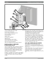
Figure # 18 

[1] Line voltage disconnect (unit)
[2] Flex duct Connection
[3] Low voltage control connection
[4] Line voltage connection
[5] Vibration pad
[6] P/T ports
[7] Hose kits (optional)
[8] Ball valves
[9] Solenoid valve slow closing
[10] Condensate drain connection
[11] Pressure tank (optional)
[12] Line voltage disconnect (electric heater)

INSTALLATION OF PRESSURE 
REGULATING VALVES

Pressure regulating valves are used to increase or
decrease water flow through the heat pump in 
response to refrigerant pressure. In some cases 
more water may be required in heating than in 
cooling, or vice versa. With the ES heat pumps 
these valves are not required. 
However, if installed, a pair of valves are required 
for proper operation, one valve for cooling (direct 
acting) and another valve for heating (indirect 
acting).

A refrigerant tap is provided in the refrigerant line 
located between the reversing valve and the water-
to-refrigerant heat exchanger for proper 
monitoring of the refrigerant pressures.
The discharge water from the heat pump is not
contaminated in any manner and can be disposed 
of in various ways depending on local building 
codes (i.e. discharge well, dry well, storm sewer, 
drain field, stream or pond, etc.) Most local codes 
forbid the use of a sanitary sewer for disposal.
Consult your local building and zoning department 
to insure compliance in your area.

COOLING TOWER/BOILER SYSTEMS

The cooling tower and boiler water loop 
temperature is usually maintained between 50° F 
to 100 ° F to assure adequate cooling and heating 
performance.
In the cooling mode, heat is rejected from the unit 
into the water loop. A cooling tower provides 
evaporative cooling to the loop water thus 
maintaining a constant supply temperature to the 
unit. 

1

2

3

4

5

6

7

8

9

10

11

12

Summary of Contents for ES025

Page 1: ...Installation and Maintenance Manual ES Series Heat Pump T111970 291 01 2015 ES025 ES035 ES049 ESO61 ES071 ...

Page 2: ...Package Option 15 Heat Recovery Package 16 Water Tank Preparation 16 HR Water Piping 16 Water Tank Refill 17 Initial Start Up 17 Hot Gas Reheat HGRH 17 Sequence of Operation 18 Cooling Mode 18 Heating Mode 18 Application considerations 18 Well Water Systems 18 Installation of Pressure Regulating Valves 19 Cooling Tower Boiler Systems 19 Geothermal Earth Coupled Systems 21 System Checkout 22 Unit S...

Page 3: ... Left Transformer R Right 7 75 VA 1 100 VA Discharge Air Configuration T Top Refrigeration Circuit Options S Straight X None E End H Hot Gas Reheat On Off B Bottom B Hot Gas Bypass C Hot Gas Bypass with Hot Gas Reheat Fan Motor Options D Heat Recovery Package A Constant Airflow ECM S Straight Cool Air Coil General Electrical Options up to 5 available per unit U Uncoated A EMS relay T Tin Plated B ...

Page 4: ...d servicing of this equipment can be hazardous due to system pressure and electrical components Only trained and qualified personnel should install repair or service the equipment WARNING Before performing service or maintenance operations on the system turn off main power to the unit Electrical shock could cause personal injury or death CAUTION When working on equipment always observe precautions...

Page 5: ...ing Refer to the hanging bracket assembly and installation instructions for details Horizontal units installed above the ceiling must conform to all local codes An auxiliary drain pan if required by code should be at least four inches larger than the bottom of the heat pump Some applications require an attic floor installation of the horizontal unit In this case the unit should be set in a full si...

Page 6: ...installed shown in Figure 5 Figure 5 2 Mount 4 Brackets to unit corner post using the bolts provided in the kit as shown on Figure 6 Figure 6 3 Install rubber grommet onto the Brackets as shown in Figure 7 4 Hang the unit and assemble the field provided threaded rod nuts and washers on to the brackets as shown in Figure 7 Figure 7 NOTE IF unit is located in a crawl space the bottom of the unit MUS...

Page 7: ...lated with a minimum of one inch duct insulation to avoid heat loss or gain and prevent condensate forming during the cooling operation If the unit will be installed in a new installation which includes new duct work the installation should be designed using current ASHRAE procedures for duct sizing If the unit is to be connected to existing duct work a check should be made to assure that the duct...

Page 8: ...nit is provided with a concentric knock out for attaching common trade sizes of conduit route power supply wiring through this opening Always connect the ground lead to the grounding lug provided in the control box and power leads to the line side of compressor contactor as indicated on the wiring diagram and Figure 5 NOTE Never use flexible hoses of a smaller inside diameter than that of the flui...

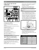
Page 9: ...rmostat connection block are a row of 2 red and 4 green LED s These LED s indicate the operating status of the unit They are labeled as follows Y1 First Stage Compressor Operation Y2 Second Stage Compressor Operation G Fan O Reversing Valve energized in cooling W1 Auxiliary Electric Heat runs in conjunction with compressor EM W2 Emergency Heat electric heat only NC Transformer 24 VAC Common extra ...

Page 10: ...roper program in the ECM motor for the unit Refer to Figure 7 for the proper jumper placement To the left of the red and green status LED s is a row of 1 4 male quick connects These are used to pass thermostat inputs on to the rest of the control circuit EM Red Emergency Heat On W1 Red Auxiliary Heat On O Green Reversing Valve Energized unit is in Cooling Mode Y2 Green Second Stage Compressor On Y...

Page 11: ...ted in the unit refrigerant suction line and wired across terminals LPC1 and LPC2 on the UPM Water side freeze protection sensor mounted close to condensing water coil monitors refrigerant temperature between condensing water coil and thermal expansion valve If temperature drops below or remains at freeze limit trip for 30 seconds the controller will shut down the compressor and enter into a soft ...

Page 12: ...curred and the unit requires inspection to determine the type of fault If it is set to PULSE a pulse signal is produced and a fault code is detected by a remote device indicating the fault See L E D Fault Indication below for blink code explanation The remote device must have a malfunction detection capability when the UPM board is set to PULSE DISPLAY OUTPUT The Display output is a pulse output c...

Page 13: ...dicate the cause of the fault If the fault condition still exists or occurs 2 or 4 times depending on 2 or 4 setting for Lockout dip switch before 60 minutes the unit will go into a hard lockout and requires a manual lockout reset A single condensate overflow fault will cause the unit to go into a hard lockout immediately and will require a manual lockout reset LOCKOUT RESET A hard lockout can be ...

Page 14: ...LED SOFT LOCKOUT RECORD ALARM START COUNTER IF APPLICABLE CC OUTPUT ON NO YES LPC CLOSED FRZ TEMP LIMIT Y1 ON TIME 30 SEC CON 0 POWER SWITCHES SENSOR STATUS CHECK START TIMER NO YES NO YES NO YES T ASC OR RS SEC YES NO TIME 120 SEC START TIMER NO YES NO YES START ANTI SHORT CYCLE INITIAL POWER UP YES NO START RANDOM START UP START COUNTER NEEDED YES COUNT 2 OR COUNT 4 BLINK CODE ON STATUS LED DISP...

Page 15: ... separate from the heat pump s power supply DO NOT attempt to wire the package into the same circuit as the heat pump NOTE If heat recovery unit is installed in an area where freezing may occur the unit must be drained during winter months to prevent heat exchanger damage Heat exchanger ruptures that occur due to freezing will void the heat recovery package warranty along with the heat pump warran...

Page 16: ...onnection and run other end of hose out doors or to an open drain 3 Close cold water inlet valve to water heater tank 4 Drain tank by opening drain valve on the bottom of the tank then open pressure relief valve or hot water faucet 5 OnES drained the tank should be flushed with cold water until the water leaving the drain hose is clear and free of sediment 6 Close all valves and remove the drain h...

Page 17: ...N position The pump will operate if entering water temperature to HR is below 120 F 3 The temperature difference between the water entering and leaving the heat recovery should be 5 to 15 F 4 Allow the unit to operate for 20 to 30 minutes to ensure it is functioning properly The pump should shut off when the water temperature entering the heat recovery reaches 120 F Hot Gas Reheat HGRH Hot gas reh...

Page 18: ...an ramps down either fan only mode or off over a span of 30 seconds If thermostat has two different output points one for Auxiliary heat and a different one for Emergency heat the two outputs must be terminated on W1 units equipped with one stage of Electric heat Figure APPLICATION CONSIDERATIONS Well Water Systems Copper is adequate for ground water that is not high in mineral content Should your...

Page 19: ...irect acting and another valve for heating indirect acting A refrigerant tap is provided in the refrigerant line located between the reversing valve and the water to refrigerant heat exchanger for proper monitoring of the refrigerant pressures The discharge water from the heat pump is not contaminated in any manner and can be disposed of in various ways depending on local building codes i e discha...

Page 20: ...eturn lines for unit isolation and unit water flow balancing Pressure temperature ports are recommended in both supply and return lines for system flow balancing Water flow can be accurately set by measuring the water to refrigerant heat exchangers water side pressure drop See specification sheets for water flow vs pressure drop information Supply and return hoses should be connected together duri...

Page 21: ...GLP makes the installation easy Anti freeze solutions are utilized when low evaporating conditions are expected to occur Refer to the GLP installation manuals for more specific instructions Figure 20 Figure 20 1 Line voltage disconnect unit 2 Flex duct Connection 3 Low voltage control connection 4 Line voltage connection unit 5 P T ports 6 Vibration pad 7 Condensate drain connection 8 Ground loop ...

Page 22: ...tch to the AUTO position The reversing valve solenoid should energize The compressor and fan should not run 3 Reduce the thermostat setting approximately 5 degrees below the room temperature 4 Verify the heat pump is operating in the cooling mode 5 Turn the thermostat system switch to the OFF position The unit should stop running and the reversing valve should de energize 6 Leave the unit off for ...

Page 23: ...ushing to insure proper drainage 5 Periodic lockouts almost always are caused by air or water flow problems The lockout shutdown of the unit is a normal protective measure in the design of the equipment If continual lockouts occur call a mechanic immediately and have them check for water flow problems water temperature problems air flow problems or air temperature problems Use of the pressure and ...

Page 24: ...__ Fluid Flow gpm ______________________________ ______________________________ Compressor Volts Amps _______________ _____________ _______________ _____________ Blower Motor Volts Amps _______________ _____________ _______________ _____________ SourES Fluid Type ______________________________ ______________________________ Fluid Flow gpm ______________________________ ____________________________...

Page 25: ...mperature setting the unit should run in the cooling mode reversing valve energized Set unit to HEAT and the highest temperature setting the unit should run in the heating mode If neither the blower or compressor run in all three cases the thermostat could be miswired or faulty To ensure miswired or faulty thermostat verify 24 volts is available on the condensing section low voltage terminal strip...

Page 26: ...or cooling loads Thermostat Thermostat installed near a supply air grill relocate thermostat Readjust heat anticipator Wiring and controls Check for defective or improperly calibrated low pressure switch INSUFFICIENT COOLING OR HEATING Unit undersized Recalculate heating and or cooling loads If excessive possibly adding insulation and shading will rectify the problem Loss of conditioned air by lea...

Page 27: ...tor 1 Run capacitor has failed may not be bad verify 2 Low line voltage contact utility if voltage at disconnect is low Check wiring connections 3 Excessive liquid refrigerant in compressor 4 Compressor bearings are seized Measure compressor oil level YELLOW ALERT FLASH CODE 5 Open Circuit 1 Outdoor unit power disconnect is open 2 Compressor circuit breaker or fuse s is open 3 Compressor contactor...

Page 28: ...oltage Control circuit 17VAC 1 Control circuit transformer is overloaded 2 Low line voltage contact utility if voltage at disconnect is low Check wiring connections Flash Code number corresponds to a number of LED flashes followed by a pause and then repeated TRIP and ALERT LEDs flashing at same time means control circuit voltage is too low for operation Comfort Alert Module Flash Codes Status LED...

Page 29: ...ths may cause shorts and insert the thermostat wires into the connector as shown Tighten the screws to ensure secure connections The thermostat has the same type connectors requiring the same wiring See instructions in the thermostat for detailed installation and operation information Figure 21 Thermostat Wiring Figure 22 NOTE When using a 2 cool 3 heat thermostat W1 and W2 EM must be connected to...

Page 30: ... 15 15 18 4 146 177 378 459 7 9 16 19 ES025 Full Load 30 4 76 92 242 297 3 4 13 14 6 80 97 249 304 2 3 13 15 40 4 125 151 180 221 14 18 19 22 89 108 255 312 4 5 15 17 6 120 146 169 207 8 10 20 23 93 113 261 320 3 3 16 18 50 4 134 163 211 258 14 18 18 21 106 118 267 327 5 6 17 19 6 129 157 198 242 8 10 19 23 110 126 274 335 3 4 18 21 60 4 139 169 241 295 14 17 18 21 113 138 280 342 6 7 19 22 6 134 ...

Page 31: ... 210 8 10 20 24 91 111 263 322 3 3 16 19 50 4 5 131 160 214 261 14 18 18 22 95 105 269 329 5 6 17 20 9 0 126 154 201 245 8 10 19 24 100 125 276 337 3 4 18 22 60 4 5 136 166 244 298 14 17 18 22 111 136 282 344 6 7 19 23 9 0 131 160 230 281 8 10 19 23 117 143 289 353 4 5 20 24 70 4 5 141 172 275 336 14 17 17 21 124 152 294 360 7 8 21 25 9 0 135 165 258 316 8 10 18 22 131 160 302 369 5 6 22 27 80 4 5...

Page 32: ...113 138 182 223 12 14 20 24 88 108 299 365 5 6 19 23 50 6 0 127 155 226 276 21 25 18 22 92 110 305 373 9 11 20 25 12 0 122 149 213 260 12 14 19 24 98 120 313 383 6 7 21 26 60 6 0 131 160 259 316 21 25 18 22 108 132 320 391 10 13 23 28 12 0 126 154 243 297 12 14 19 23 113 138 328 400 7 9 24 29 70 6 0 136 166 291 355 20 25 17 21 120 147 334 408 12 15 25 31 12 0 130 159 273 334 12 14 18 22 126 154 34...

Page 33: ... 11 14 22 27 86 105 283 346 5 6 23 28 50 7 0 120 147 215 263 15 18 20 25 93 114 299 365 8 9 24 29 14 0 117 143 201 246 11 14 21 26 99 121 305 373 6 7 25 31 60 7 0 123 150 248 304 14 17 20 24 106 129 321 392 9 11 26 32 14 0 119 146 232 284 11 13 21 25 113 138 327 400 7 8 28 34 70 7 0 126 154 282 344 14 17 19 24 118 145 342 418 10 12 29 35 14 0 122 149 263 322 10 13 20 25 126 154 349 427 8 9 30 37 8...

Page 34: ...6 16 0 117 142 173 211 11 14 22 27 89 108 286 349 5 6 23 28 50 10 123 150 218 266 15 18 20 25 96 117 302 368 8 9 24 29 16 0 120 146 204 249 11 14 21 26 102 124 308 376 6 7 25 31 60 10 126 153 251 307 14 17 20 24 109 132 324 395 9 11 26 32 16 0 122 149 235 287 11 13 21 25 116 141 330 403 7 8 28 34 70 10 129 157 285 347 14 17 19 24 121 148 345 421 10 12 29 35 16 0 125 152 266 325 10 13 20 25 129 157...

Page 35: ...100 1100 1100 1100 1100 1100 1100 1100 1100 Med 925 Normal B 925 925 925 925 925 925 925 925 925 925 Low 800 B 800 800 800 800 800 800 800 800 800 800 049 Full Load Hi 1700 B 1700 1700 1700 1700 1700 1700 1700 1700 1700 1700 Med 1500 Normal B 1500 1500 1500 1500 1500 1500 1500 1500 1500 1500 Low 1275 B 1275 1275 1275 1275 1275 1275 1275 1275 1275 1275 061 Part Load Hi 1725 A 1725 1725 1725 1725 17...

Page 36: ... Series ES Series T111970291 2015 01 Subject to change without prior notice WIRING DIAGRAMS Figure 23 FOR REFERENCE ONLY Actual unit wiring may vary from this example Always refer to the wiring diagram attached to the unit ...

Page 37: ...Wiring diagrams 37 ES Series T111970291 2015 01 ES Series Figure 24 FOR REFERENCE ONLY Actual unit wiring may vary from this example Always refer to the wiring diagram attached to the unit ...

Page 38: ...grams ES Series ES Series T111970291 2015 01 Subject to change without prior notice Figure 25 FOR REFERENCE ONLY Actual unit wiring may vary from this example Always refer to the wiring diagram attached to the unit ...

Page 39: ...Wiring diagrams 39 ES Series T111970291 2015 01 ES Series Figure 26 FOR REFERENCE ONLY Actual unit wiring may vary from this example Always refer to the wiring diagram attached to the unit ...

Page 40: ...grams ES Series ES Series T111970291 2015 01 Subject to change without prior notice Figure 27 FOR REFERENCE ONLY Actual unit wiring may vary from this example Always refer to the wiring diagram attached to the unit ...

Page 41: ...Wiring diagrams 41 ES Series T111970291 2015 01 ES Series Figure 28 FOR REFERENCE ONLY Actual unit wiring may vary from this example Always refer to the wiring diagram attached to the unit ...

Page 42: ...grams ES Series ES Series T111970291 2015 01 Subject to change without prior notice Figure 29 FOR REFERENCE ONLY Actual unit wiring may vary from this example Always refer to the wiring diagram attached to the unit ...

Page 43: ...Wiring diagrams 43 ES Series T111970291 2015 01 ES Series Figure 30 FOR REFERENCE ONLY Actual unit wiring may vary from this example Always refer to the wiring diagram attached to the unit ...

Page 44: ...grams ES Series ES Series T111970291 2015 01 Subject to change without prior notice Figure 31 FOR REFERENCE ONLY Actual unit wiring may vary from this example Always refer to the wiring diagram attached to the unit ...

Page 45: ...Wiring diagrams 45 ES Series T111970291 2015 01 ES Series Figure 32 FOR REFERENCE ONLY Actual unit wiring may vary from this example Always refer to the wiring diagram attached to the unit ...

Page 46: ...46 Notes ES Series ES Series T111970291 2015 01 Subject to change without prior notice NOTES ...

Page 47: ...Notes 47 ES Series T111970291 2015 01 ES Series ...

Page 48: ...Bosch Thermotechnology Corp 555 NW 65th Court Ft Lauderdale FL 33309 Phone 954 776 5471 Fax 954 776 5529 www bosch climate us Revised 01 2015 ...

Reviews: