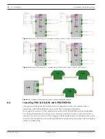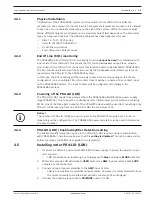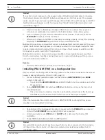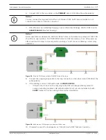
Loudspeaker line isolator system
Installation | en
13
Bosch Security Systems B.V.
Installation manual
2021.07.28 | V1.00 |
4
Installation
The loudspeaker line isolator system can be installed on both new and existing loudspeaker
line installations.
Several conditions
need to be met first
to make all features work properly:
–
Main loudspeaker line has to be a
closed loop
.
–
T‑branch lines fitted with multiple loudspeakers require
47 kΩ EOL resistor
for T‑Branch
open detection.
–
Every loudspeaker connected to Line isolator needs to be equipped with
DC‑blocking
capacitor
(typical value is
1 ~ 4.7 μF
).
–
For
100 V
installations maximum total load of single loop is
800 W
, maximum single
T‑Branch load
50 W
.
–
24 or 48 VDC
power supply
for LDB.
4.1
Fault contact
Line isolator provides fault contact output per loudspeaker line for integration with any Voice
Alarm System via programmable
control inputs
. Every loudspeaker line can have separate
contact closure, or - depending on the system design - multiple loudspeaker lines can share
common fault contact.
The contact is
normally open
during
quiescent
mode of the system. During
quiescent
mode:
–
Line isolator system is powered and running, monitoring entire loudspeaker line.
–
Power amplifier is connected.
–
Loop is closed and fully working, every T‑Branch is fully operational.
–
No faults detected.
Any other state, including
service
mode, amplifier disconnection or even power failure of Line
isolator, will immediately close the contact, reporting failure to the main system.
4.2
Wiring
The loudspeaker line isolator system can connect to solid-core wires or stranded wires with
conductor diameter of
0.8 - 2.5 mm2
. The maximum current rating of the loudspeaker loop is
8 A RMS
, which allows loading single
100 V
line up to
800 W
.
Fully functional when running on 2‑wire loudspeaker cable. For installations with special safety
requirements, its supports optional ground wire with open detection.
Maximum length of loop cabling is
1000 m
. Maximum length of T‑Branch line is also
1000 m
.
4.3
Wiring configurations
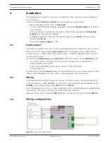
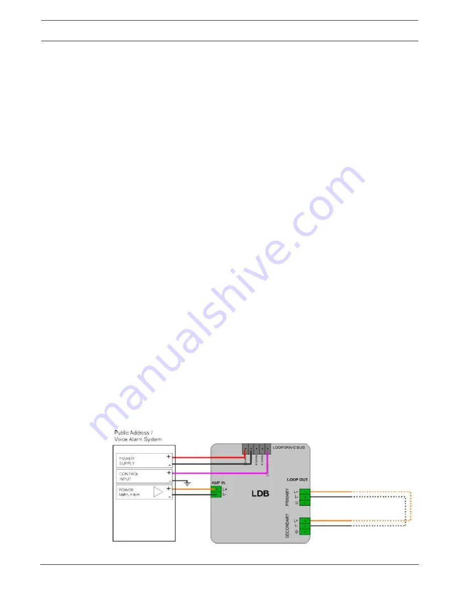
Figure 4.1:
Single LDB wiring diagram
Summary of Contents for F.01U.393.727
Page 1: ...Loudspeaker line isolator system PRAESENSA en Installation manual ...
Page 2: ......
Page 37: ......

