background image

4

en | Table of Contents

Conventional Automatic Detectors

F.01U.002.707 | 8.0 | 2011.10

Operation Guide

Bosch Sicherheitssysteme GmbH

6.6

Service Accessories

25

7

Maintenance and Service

26

7.1

Coding of the Detector Types

27

7.2

Test Procedure for Detectors with C-Sensor

27

7.3

Test Procedure for Detectors without C-Sensor

28

7.4

Warranty

28

7.5

Repair

28

7.6

Disposal

28

7.7

Additional Documentation

28

8

Specifications

29

I

Abbreviations

31

Summary of Contents for FCH?320

Page 1: ...Conventional Automatic Detectors FCP 320 FCH 320 en Operation Guide ...

Page 2: ......

Page 3: ... 400 B 12 4 3 2 Wiring the MSR 320 13 4 4 Detector Base Sounder 14 4 5 Installing the Detector Head 14 4 6 Detector Removal 15 5 Accessories 16 5 1 EOL Module for Line Termination According to EN 54 13 16 5 2 Support Plates for Detector Identification 16 5 3 SK 400 Protective Basket 16 5 4 SSK 400 Protective Dust Cover 17 5 5 MK 400 Detector Console 17 5 6 MH 400 Detector Heating Element 17 5 7 Ex...

Page 4: ...eme GmbH 6 6 Service Accessories 25 7 Maintenance and Service 26 7 1 Coding of the Detector Types 27 7 2 Test Procedure for Detectors with C Sensor 27 7 3 Test Procedure for Detectors without C Sensor 28 7 4 Warranty 28 7 5 Repair 28 7 6 Disposal 28 7 7 Additional Documentation 28 8 Specifications 29 I Abbreviations 31 ...

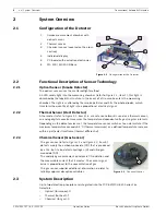
Page 5: ...ration between engineers and designers With this design it is possible to reconcile the contradictory goals of a generous installation space and a small detector The placement of the individual display on the detector tip is the first externally visible characteristic of the installation friendly development concept The stable and robust detector base need no longer be aligned due to the position ...

Page 6: ...perature sensor switches to an alarm state if the maximum temperature exceeds 54 C thermal maximum or a defined temperature increase within a particular timeframe thermal differential 2 2 3 Chemical Sensor Gas Sensor 2 3 System Description Up to two detection principles are integrated into the FCP 320 FCH 320 Series Fire Detectors Optical for smoke O Thermal for heat T Chemical for gas C 1 Smoke m...

Page 7: ... an alarm in the case of smoke as well as in the case of a temperature rise Additionally the threshold of the optical sensor is adjusted in accordance with the absolute temperature and the rate of temperature rise 2 4 Features Active adjustment of the threshold drift compensation if the optical sensor becomes contaminated Active adjustment of the threshold drift compensation of the chemical sensor...

Page 8: ... Maximum permitted air speed 20 m s A maximum of 32 detectors can be connected per primary line This number is limited to 20 detectors when connected to an UGM 2020 GIF GIF2 3 2 Use in Fire Barriers Conforming to DIBt The FCH T320 FSA and FCP O320 are available for use in fire barriers conforming to the guideline of the DIBt Deutsches Institut für Bautechnik German Institute for Building Technolog...

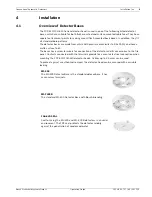
Page 9: ... to RAL 9010 and have a matte surface finish The bases have screw terminals for connection of the detector and its accessories to the fire panel Contacts connected with the terminals provide for a secure electrical connection when mounting the FCP 320 FCH 320 detector heads Cables up to 2 5 mm2 can be used To protect against unauthorized removal the detector head can be secured with a variable loc...

Page 10: ...olders etc MSC 420 The MSC 420 Additional Base was designed specially for surface mounted cable feed via cable protection conduits It is used in combination with any of the above listed bases It has two opposing pre cut inlets of 20 mm diameter and two additional opposing and prepared inlets for up to 28 mm diameter The additional base has a diameter of 120 mm and a height of 36 7 mm To protect ag...

Page 11: ...ce mounting break out the prepared entry points X on the housing In the case of flush mounted cable feed route the cable through the opening in the centre of the base The short mounting bores marked in the sketch with Y may be used only for fixing over a back box NOTICE Cable feed and outfeed can be on the same side For cable feed at the FAA 420 SEAL and MSC 420 puncture the sealing with a pointed...

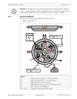
Page 12: ... it Legend ye yellow connects to b1 b2 L b conventional wh white connects to a1 a2 L a conventional rd red connects to V bk black connects to 0V gn green connects to shielding wire c Indicator output V 0V Terminals for looping through the power supply to subsequent elements MPA FAA 420 RI External Detector Alarm Display Remote Indicator MPA FAA 420 RI max 3 m C a1 a2 LSN L a LSN L b rd bk max 30 V...

Page 13: ...tor base or with an FLM 320 EOL2W EOL module For terminating the line according to the EN 54 13 standard the FLM 320 EOL2W EOL module is required Legend ye yellow connects to b1 b2 L b conventional wh white connects to a1 a2 L a conventional rd MPA FAA 420 RI red connects to b1 bk MPA FAA 420 RI black connects to c Indicator output gn green connects to shielding wire NC C NO Changeover relay for t...

Page 14: ...xternal Detector Alarm Display Remote Indicator Legend NOTICE The last detector in a conventional line can be terminated either with a terminal resistor in the detector base or with an FLM 320 EOL2W EOL module For terminating the line according to the EN 54 13 standard the FLM 320 EOL2W EOL module is required MSS 300 Detector Base Sounder white for conventional technology connection via the detect...

Page 15: ...bled by turning them to the left and removing them from the base Locked detector heads are disassembled by inserting a screwdriver into the unlocking opening Y so that the bolt is pushed upward at the same time the detector head should be turned to the left refer to Figure 4 2 Figure 4 2 Detector Removal Locked Detector Legend 1 Bolt X prior to breaking out 2 Bolt X installed but inactive 3 Lockin...

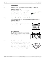
Page 16: ...smits a notification to the fire panel display For a conventional connection according to EN 54 13 one line must not contain more than 32 automatic detectors TP4 400 Support Plate The TP4 400 Support Plate is intended for an installation height up to 4 m and is designed for labels up to a size of approximately 65 x 34 mm TP8 400 Support Plate The TP8 400 Support Plate is intended for an installati...

Page 17: ...on from contamination The protective dust cover made from polypropylene PP is pushed onto the installed detector base The MK 400 Detector Console is used to install detectors above door frames or similar in compliance with DIBt The console is supplied with a pre mounted MS 400 Detector Base the detector shown is not included in the scope of delivery The MH 400 Detector Heating Element is required ...

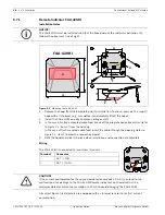
Page 18: ...sert the cable through the opening refer to Figure 5 1 item Y below the connection board 4 Refit the hood and click into place when installation and connection are complete Wiring The FAA 420 RI is connected to two screw terminals All current Bosch fire detectors are equipped with an internal resistor to restrict current consumption NOTICE The FAA 420 RI must be installed such that the broad side ...

Page 19: ...onnected to the Wago clamps 1 to 4 Connect Put in the isolated wire no braid into the clamp Disconnect Pull the wire out of the clamp by turning it back and forth You can connect up to four detectors onto each MPA NOTICE The cable length between the detector and the FAA 420 RI must not exceed 3 m when connected by an unscreened cable Technical Specification FAA 420 RI Operating voltage 5 V DC to 3...

Page 20: ...LED could be destroyed All current Bosch fire detectors are equipped with an internal resistor to restrict current consumption 1 2 3 4 CAUTION If the current consumption for the connected detector exceeds 20 mA it can lead to the malfunction of or damage to the MPA External Detector Alarm Display You should restrict the maximum detector current consumption to 20 mA to avoid damaging the FAA 420 RI...

Page 21: ... gripping of fire detectors and thus also protect the detector surface against damage RTL cap Plastic Caps for the SOLO200 Detector Removal Tool Scope of delivery 2 pieces SOLO330 Smoke Detector Tester Use the SOLO330 Smoke Detector Tester for in place testing of smoke detectors using an aerosol designed to simulate smoke particles SOLO A3 001 Test Aerosol for Optical Smoke Detectors Spray with 25...

Page 22: ... multi sensor detectors and multi criteria detectors Testing stimuli heat smoke and carbon monoxide are created without using pressurized aerosol cans or hazardous media Testing stimuli are generated at the time of test using safe and patented processes fuelled by replaceable capsules FME TS3 Smoke Capsule Smoke Capsule for FME TESTIFIRE testing tool FME TC3 CO Capsule CO Capsule for FME TESTIFIRE...

Page 23: ...ension Poles It also can be used with the SOLO100 Telescopic Access Pole The Fixed Extension Pole withstands high voltage situations and is checked for safety compliance in accordance with the requirements of BS EN 61235 Section 12 using an applied voltage of 20 kV Length 1 m SOLO610 Test Equipment Bag The SOLO610 Test Equipment Bag is made of sturdy woven polyester with a PVC coating for carrying...

Page 24: ...r Detector Optical Thermal F 01U 029 862 FCP O320 R470 Optical Smoke Detector F 01U 029 857 FCH T320 R470 Heat Detector F 01U 029 861 Type Number Designation Product ID MS 400 Standard Detector Base for surface mounted and flush mounted cable feed 4 998 021 535 MS 400 B Standard Detector Base for surface mounted and flush mounted cable feed with Bosch branding F 01U 215 139 FAA 420 SEAL Damp Room ...

Page 25: ...unted and flush mounted cable feed 4 998 025 372 MSS 300 WS EC Detector Base Sounder White only for separate activation e g via Interface Module for surface mounted and flush mounted cable feed 4 998 120 501 Type Number Designation Product ID SOLO200 Detector Removal Tool 4 998 112 113 RTL cap Plastic Caps for the SOLO200 Detector Removal Tool Scope of delivery 2 pieces 4 998 082 502 SOLO330 Smoke...

Page 26: ...tion due to the gas sensor s limited life cycle The detector continues to function as an O detector Depending on the system there may be no message to the control panel and the deactivation of the C sensor is only noticed when the detector is tested The FCP OC320 FCP OC320 R470 should therefore be exchanged promptly before 5 years of operation has elapsed Optical smoke detectors should depending o...

Page 27: ...rox one minute 1 Position the Smoke Detector Tester on the FCP OC320 2 Spray aerosol 1 to 2 seconds Do not remove the test device from the detector the O sensor triggers only approx 60 seconds after the application of the test aerosol 3 Reset detector This switches the detector to revision mode 4 Place CO Testing Gas bottle in the test device 5 Position test device on the detector 6 Apply CO gas f...

Page 28: ...changed free of charge in the case of a claim under the warranty 7 5 Repair In the event of a defect the entire detector is exchanged 7 6 Disposal FCP OC320 Packaging Film The packaging bag used for multisensor detectors with C sensor consists of tear resistant PE ALU laminated film and may be disposed of with the household refuse Defective detectors are exchanged and should be disposed of in acco...

Page 29: ... 0 V via 3 92 kΩ max 8 mA Response sensitivity basic data Optical sensor 0 15 dB m EN54 7 Chemical sensor ppm range Optical sensor 0 15 dB m EN54 7 Thermal sensor Class A2R acc to EN 54 5 Thermal maximum unit 54 C Thermal differential unit refer to table Page 30 Max monitoring range 120 m2 observe VdS guidelines Maximum installation height 16 m observe VdS guidelines Permissible air speed 20 m s P...

Page 30: ...cc to EN 54 5V Thermal max unit 54 C Thermal diff unit refer to table Page 30 Max monitoring range 120 m2 observe VdS guidelines 40 m2 observe VdS guidelines Maximum installation height 16 m observe VdS guidelines 6 m observe VdS guidelines Permissible air speed 20 m s Permissible operating temp 20 C 65 C 20 C 50 C Permissible relative humidity 95 non condensing Protection category according to EN...

Page 31: ...sec ABS Acrylonitrile butadiene styrene DIBt Deutsches Institut für Bautechnik German Institute for Building Technology DIN Deutsches Institut für Normung e V German Institute for Standardization EN European Standard GLT Conventional technology LED Light Emitting Diode LSN Local SecurityNetwork PI Product information PP Polypropylene UEZ Universelle Europazentrale Universal European Fire Panel UGM...

Page 32: ......

Page 33: ......
Page 34: ...Bosch Sicherheitssysteme GmbH Robert Bosch Ring 5 85630 Grasbrunn Germany www boschsecurity com Bosch Sicherheitssysteme GmbH 2011 ...

Reviews: