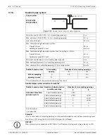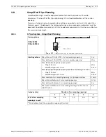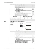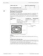
60
en | Installing the Aspirating Smoke Detector
FCS-320-TM Aspirating Smoke Detector
F.01U.130.928 | 1.0 | 2009.11
Operation Guide
Bosch Sicherheitssysteme GmbH
4.4
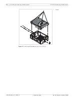
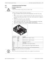
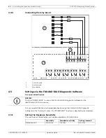
Installation and electrical connection of auxiliary modules
4.4.1
Installing the reset board
The reset board is optionally available for use with the FCS-320-TM series. The reset board is
installed in an appropriate additional housing. If several FCS-320-TMs are connected to one
detector line, the reset board is installed in the detector line after the last FCS-320-TM unit.
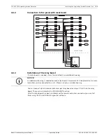
The reset board electrically connected in accordance with the wiring diagram (see Fig. 5.10).
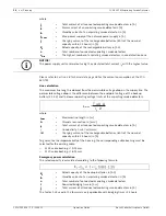
Standby current of the line
Calculate the standby current I
R
of the line as follows:
where
R
E
= original terminal resistance of the line [Ohm]
U
L
= Line voltage [V]
I
R
= Standby current of the line [A]
The equations used to calculate the terminal resistance and the standby current of the
detector line are based on an ideal condition for signal evaluation.
If acknowledgement does not take place with the calculated terminal resistance for the relay
board, reduce the value of the terminal resistance by approx. 20%.
Terminal resistance
The reset board simulates the detector line terminal resistance. It is calculated anew and
installed on the reset board (Terminal X1). Calculate the value of the terminal resistance R
ER
as follows:
where
R
ER
= Terminal resistance on the reset board [Ohms]
U
L
= Line voltage [V]
I
R
= Standby current of the line [A]
NOTICE!
The reset board can be used only if the standby current of the detector line is between 5 mA
and 50 mA and the detector line terminates with a resistor. The reset pulse is triggered
whenever the line voltage drops below 3 V when resetting the panel.
E
L
R
R
U
I =
(
)
R
L
ER
I
R
−
=
U
2,7 V
Summary of Contents for FCS-320-TM
Page 1: ...FCS 320 TM Aspirating Smoke Detector FCS 320 TM FCS 320 TM R en Operation Guide ...
Page 2: ......
Page 99: ......

