background image

 Installation Instructions

Linear Smoke Detector Fireray 50/100RV

ST/PMF/zab

610- F.01U.002.706 / A2.en

Page 4  of  14

Plug connector

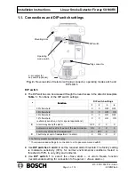
The plug connector can be accessed through the oval recess on the detector base plate.
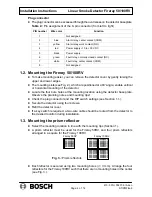
Table 2.: Pin assignment of the 8 - pin connector (from left to right)

PIN number

Wire color

Function

1

Not assigned

2

blue

Alarm relay, center contact (COM)

3

yellow

Alarm relay, work contact (NO)

4

red

Power 10 to +30 V DC

5

black

Power supply  -

6

green

Fault relay, normally closed contact (NC)

7

white

Fault relay, center contact (COM)

8

Not assigned

1.2. Mounting the Fireray 50/100RV

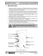
To make mounting easier, you can remove the detector cover by gently raising the
upper and lower edges.

The mounting slots (see Fig. 2.), which are positioned at a 90

angle, enable vertical

or horizontal mounting of the detector.

Locate the four bore holes at the mounting location using the detector base plate.
Observe the planning notes and mounting tips!

Check the plug connector and the DIP switch settings (see Section 1.1.).

Secure the detector using four screws.

Refit the detector cover.

If a key switch is required, a two - wire cable should be routed from the detector to
the desired location during installation.

1.3. Mounting the prism reflector

Select the mounting location in line with the mounting tips (Section 1.).

A prism reflector must be used for the Fireray 50RV, and four prism reflectors
arranged in a square for the Fireray 100RV.

Fireray 50RV

Fireray 100RV

ÌÌÌ

ÌÌÌ

ÌÌÌ

ÌÌÌ

ÌÌÌÌ

ÌÌÌÌ

ÌÌÌÌ

ÌÌÌÌ

ÌÌÌÌ

ÌÌÌÌ

ÌÌÌÌ

ÌÌÌÌ

ÌÌÌÌ

ÌÌÌÌ

ÌÌÌÌ

ÌÌÌÌ

ÌÌÌÌ

ÌÌÌÌ

ÌÌÌÌ

ÌÌÌÌ

Fig. 3.: Prism reflectors

Each reflector is secured using two mounting bores (

Ğ

 3 mm). Arrange the four

reflectors for the Fireray 100RV such that there are no mounting holes in the center
(see Fig. 3.).

Summary of Contents for Fireray 50RV

Page 1: ...nd DIP switch settings 3 1 2 Mounting the Fireray 50 100RV 4 1 3 Mounting the prism reflector 4 1 4 Connection 5 2 Start Up 7 2 1 Setting up the detector 7 2 2 Aligning the detector 7 2 3 System test 9 3 Tips on Maintenance and Service 9 4 Technical Data 10 5 Additional Documentation 10 6 Appendices 11 6 1 Installation protocol 11 6 2 Fault diagnosis 12 6 3 Notes 13 ...

Page 2: ...on a solid surface at the permissible distance Ensure that the light beam meets the reflector on the vertical The reflectors must not be mounted on reflective surfaces such as glass or plain sheet surfaces Additional reflections lead to malfunctions For protection against radio interference use a shielded cable When you are installing the cable possible sources of disturbance must be circumvented ...

Page 3: ...5 threshold X X OFF ON 25 threshold X X ON OFF 12 threshold extremely sensitive only for special applications X X ON ON X Alarm relay saves the alarm OFF X X X Automatic reset 5 s after the end of the alarm criterion ON X X X Alarm relay after end of readjustment X OFF X X X Fault relay at end of readjustment no alarm X ON X X The factory presets are shaded in gray The recommended settings for con...

Page 4: ...tical or horizontal mounting of the detector Locate the four bore holes at the mounting location using the detector base plate Observe the planning notes and mounting tips Check the plug connector and the DIP switch settings see Section 1 1 Secure the detector using four screws Refit the detector cover If a key switch is required a two wire cable should be routed from the detector to the desired l...

Page 5: ...1 VII1 VII2 VI1 VI2 ye blk gn wh 2 2 Contacts in open position Configuration for LSN Parameterize the NSB in the control panel to control output KA1 KA2 KR R RR and Control with Fireray Operating mode switches Prism Targeting Alignment Mode Operating Mode DIP switch Functions see table 1 page 3 Output for key switch optional Operating mode switch 3K3 Connection of a Fireray 50 100RV using a NSB100...

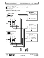
Page 6: ...0 Connection of two Fireray 50 100RV to fire panel with cross zoning via an NBK 100 LSN and two NSB100 LSNs V1 V2 Line 2 VI1 VI2 Line 1 V1 V2 Line 2 VI1 VI2 Line 1 NBK 100 LSN NSB 100 LSN V1 KR V2 KA1 V3 KA2 NSB 100 LSN V1 KR V2 KA1 V3 KA2 3k92 FAULT ALARM Power sup ply 10 30 V Fireray 50 100 RV NO COM NC COM 2 Operating mode switch 820 3k92 Parameterize e g to 127 1 Parameterize e g to KA1 KA2 KR...

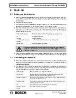
Page 7: ...ver under no circumstances must it move to other light sources or reflective surfaces Cover the prism reflector with a non reflective material to check The LED must not be lit If the yellow LED does not go out this indicates that a reflector is incorrectly aligned 2 2 Calibrating the detector Once the optimum detector set up has been achieved set the operating mode switch to the center position wi...

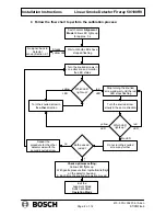
Page 8: ...op turning the knurled screw and wait until the red LED stops flashing Turn the knurled screw slowly in the same direction Turn the knurled screw in the other direction Which LED lights up Do not turn the knurled screw any further Repeat the procedure for the other detector axis with the second knurled screw Both axes ad justed Check optimum setting Yellow LED lights up 1 With gentle pressure from...

Page 9: ...receiver lens upper or right hand part of detector Select a volume of smoke slightly greater than the threshold set for the detector see Section 1 1 Make sure that you do not also cover the transmitter lens After approx 10 s the red LED must light up and the alarm relay must close With the Save alarm detector setting DIP switch 1 off there must be a reset at the control panel or the power supply m...

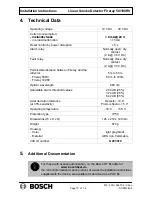
Page 10: ...eray 50RV Fireray 100RV 5 m to 50 m 50 m to 100m Optical wavelength 880 nm Adjustable alarm threshold values 2 50 dB 25 3 74 dB 35 6 02 dB 55 Axial deviation tolerance at 35 sensitivity Detector 0 8 Prism reflector 5 0 Operating temperature 30 C 55 C Protection type IP 50 Dimensions W x H x D 126 x 210 x 120 mm Weight 670 g Housing Color Material light gray black ABS non flammable VdS ID number G ...

Page 11: ..._________ m Mounting surface e g masonry rein forced concrete steel beams wood etc Serial number s Reflector size 1 x 10 x 10 cm 4 x 20 x 20 cm Supply voltage _________ V Correct mechanical adjustment of transmitter when gentle pressure is applied to the detector housing from the left right top bottom the yellow LED lights up initially yes no Alarm triggered with absorption film 35 50 tested yes n...

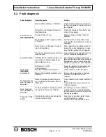
Page 12: ...er position Direct and incom plete detector set up Align detector vertically and horizon tally until the fault LED is permanently illuminated Then continue using fine adjustment switch in center position Alarm LED illuminated DIP switch 1 at OFF Save alarm the alarm display remains saved Reset the detector by disrupting the supply voltage for at least 5 s or select Reset on the fire panel illumina...

Page 13: ...______________________________________________________________ __________________________________________________________________ __________________________________________________________________ __________________________________________________________________ __________________________________________________________________ __________________________________________________________________ __...

Page 14: ...Bosch Security Systems Robert Koch Str 100 D 85521 Ottobrunn Info Service Telephone 49 89 6290 1039 Fax 49 89 6290 1039 www bosch sicherheitssysteme de info service de bosch com ...

Reviews: