-22-
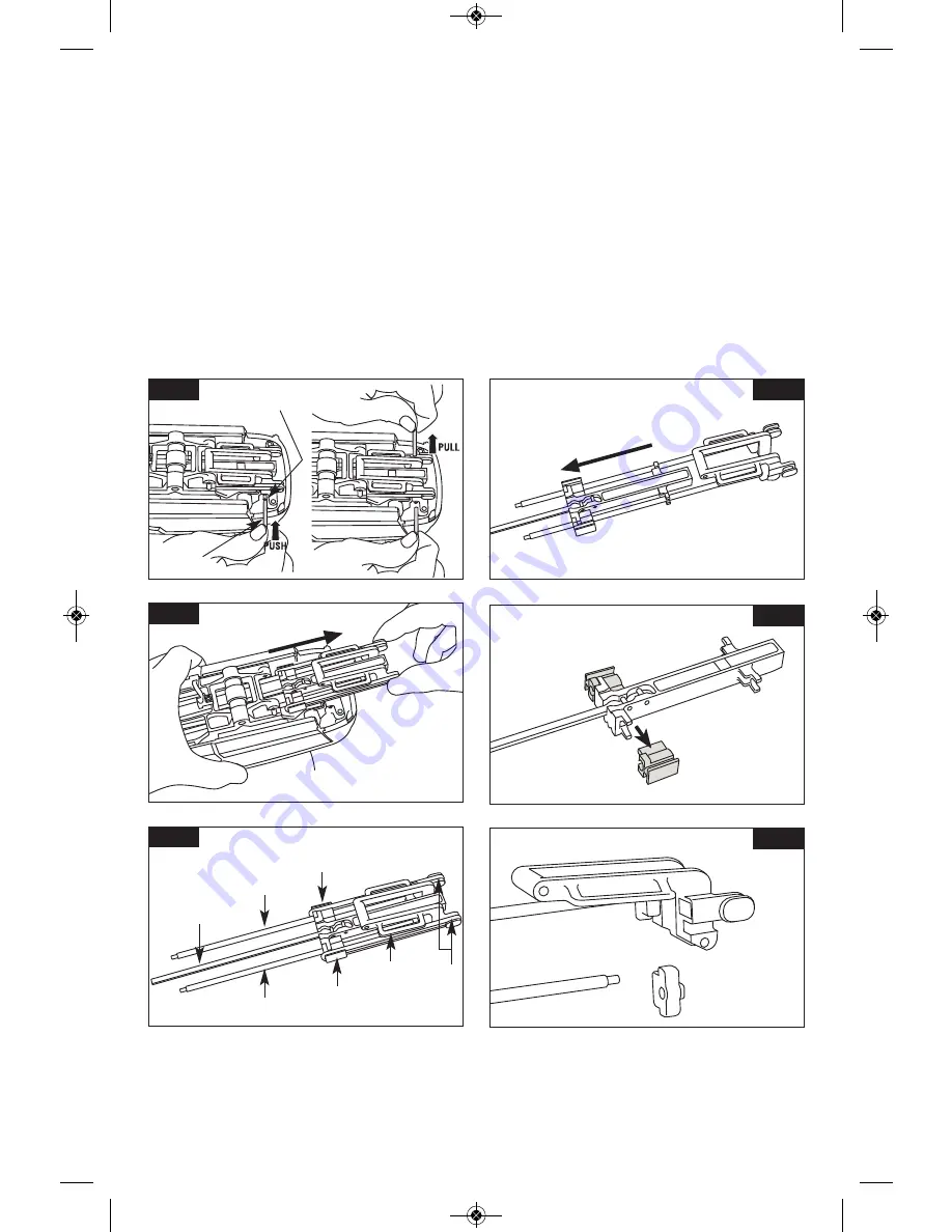
3. Locate pin #2. To remove, use pin #1 and
push pin #2 from either side until enough of
the pin has been exposed. Remove
completely. Place both pins in secure place
for reassembly (Fig. 33).
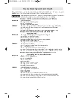
4. Remove Driver Sub Assembly. Holding tool
securely with one hand, use other hand to
remove driver sub-assembly by grabbing
both sides and then pull directly back
(Fig. 34).
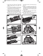
5. The Driver Sub Assembly consists of 5 parts
(Fig. 35):
A) Driver Block Assembly (1)
B) Guide Rails (2)
C) Guide Sleeves (2)
D) Return Frame (1)
E) Rubber Cords (2)
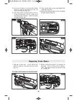
6. Remove rubber cords and pull driver block
assembly away from return frame and guide
rails (Fig. 36).
7. Remove guide sleeves away from driver
block assembly (Fig. 37).
8. If rubber bumper and guide rail become
detached from return frame, re-attach
rubber bumper and guide rail as shown
(Fig. 38).
FIG. 33
FIG. 34
FIG. 35
FIG. 36
FIG. 37
FIG. 38
B
C
B
A
C
D
E
PIN #2
PIN #1
BM 2610034445 03-14_FNH180 3/27/14 11:52 AM Page 22


