background image

4

en | General Information

FPA-1000-V2 Network Cards

2017.11 | 2.0 | F.01U.214.374

Installation manual

Bosch Security Systems, Inc.

1

General Information

1.1

Safety

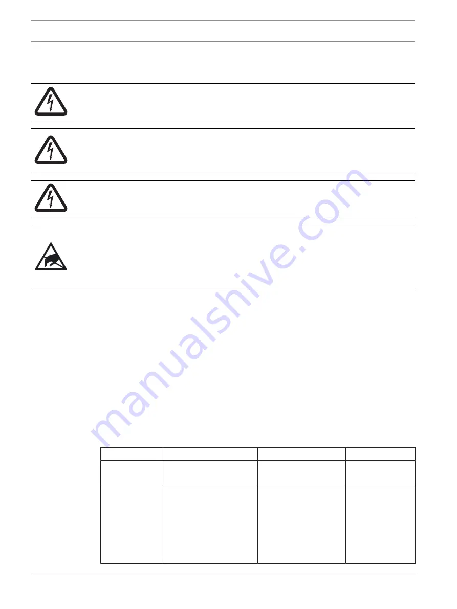
Danger!

Fire panels are life safety devices. Only trained personnel should install and program the
panels!

Danger!

Any panel in a network can control all other panels in the network (for example, silencing an
alarm or resetting the system). Access to networked panels should be restricted to properly
trained personnel.

Danger!

Make sure all power is removed before making any electrical connections. Failure to do so
may result in personal injury and/or damage to equipment.

Caution!

Static-sensitive components - ground yourself before handling
The mainboard and some modules contain static-sensitive components. Use a wrist strap
connected to ground or touch ground to discharge static electricity from your body and
continue to touch ground while unpacking or handling the mainboard and modules. Run a
ground wire to the enclosure before installing the mainboard or modules into the enclosure.

Install, test and maintain the device according to these instructions, NFPA codes, local codes,
and the authority having jurisdiction (AHJ). Failure to follow these instructions can result in
failure of the device to operate properly. Bosch Security Systems, Inc. is not responsible for
improperly installed, tested or maintained devices.
For detailed wire style requirements, see 

NFPA 72 National Fire Alarm and Signaling Code

. For

programming instructions, see the 

FPA-1000 Installation and Operation Guide

.

1.2

Network card overview

The FPA-1000-V2 panels are advanced analog addressable control panels for small to large
facilities. The panels are used in residential, commercial, or public buildings applications.
Optional network cards allow the interconnection of multiple panels into a networked system.
The network acts as a single panel for purposes of communication. In other words, an alarm
signal received by any networked panel is communicated to all the panels in the network.
Based on communication connection mode, there are three types of network cards available:

Card number

Description

Connection mode

Maximum distance

FPE-1000-NE

Ethernet network card

Three Ethernet ports

CAT 5 minimum

328


ft. (100


m)

FPE-1000-NF

Fiber optic network card

One Ethernet port 
Two fiber optic ports

CAT 5 minimum
multi-mode fiber optic
with LC connector, 
50


µm/125


µm fiber size, 

1300


nm (1270 to

1380


nm) wavelength

328


ft. (100 m) 

10


db loss 

or

6560


ft. (2000


m)

Summary of Contents for FPE-1000-NE

Page 1: ...FPA 1000 V2 Network Cards FPE 1000 NE FPE 1000 NF and FPE 1000 NW en Installation manual ...

Page 2: ......

Page 3: ...sion 7 3 Installation 8 3 1 General considerations 8 3 2 Mounting 8 4 Connection 9 4 1 General considerations 9 4 2 Interconnecting network cards 9 4 2 1 Class X Class B connections 9 4 2 2 Connecting card to card 10 4 3 Verifying network links 11 5 Panel network configuration 12 5 1 Programming the panels for networking 12 5 1 1 By keypad 12 5 1 2 By browser 13 5 1 3 By off line tool 13 5 2 Progr...

Page 4: ...d the authority having jurisdiction AHJ Failure to follow these instructions can result in failure of the device to operate properly Bosch Security Systems Inc is not responsible for improperly installed tested or maintained devices For detailed wire style requirements see NFPA 72 National Fire Alarm and Signaling Code For programming instructions see the FPA 1000 Installation and Operation Guide ...

Page 5: ... 11 2 0 F 01U 214 374 Card number Description Connection mode Maximum distance FPE 1000 NW Wired network card One Ethernet port Two wired ports CAT 5 minimum 14 AWG to 18 AWG ISO 2 5 mm2 to 0 75 mm2 plain or twisted pair wire shielded or unshielded 328 ft 100 m 3280 ft 1000 m Tab 1 1 Network card types ...

Page 6: ...electrical noise and is suitable for longer distances up to 6560 ft 2000 m The types and numbers of Networking Cards needed Interconnection requirements including the maximum allowable cable lengths which depend on the intended interconnection method Ethernet fiber optic cable or wire Before installing any devices to be connected to any networked panel be careful to plan properly Check The compati...

Page 7: ...sabled at this end of the connection making it an Ethernet OUT Remove the jumper from both pins and replace it on only one pin so that it does not get misplaced in case Ground Fault Detection needs to be re enabled later 2 3 Port supervision Each peer to peer connection to a networking card port used for panel to panel communication must be supervised This supervision is selected during programmin...

Page 8: ...e to the enclosure before handling the circuit boards Touch ground before unpacking and handling the circuit boards This discharges any static electricity in your body Continue touching the enclosure while installing the circuit boards 3 2 Mounting The main board allows for the installation of one networking card See the following figure To install the card Position the networking card along the b...

Page 9: ...ds should not be run through the same knockout as the phone lines 4 2 Interconnecting network cards 4 2 1 Class X Class B connections A network can be connected as Class X or Class B The network circuit is supervised Class X configuration is recommended because this allows the panels in a network to communicate with each other ensuring circuit operation in the event of a single fault in the wiring...

Page 10: ...xt is not connected the circuit is a Class B circuit If all connections between panels are made the circuit is Class X 4 2 2 Connecting card to card Notice Although there is an Ethernet port on the panel s Mainboard this port is reserved for programming and reporting and should not be used for peer to peer communications Peer to peer communication connections should be made from one networking car...

Page 11: ...nfiguration verify that the network link LEDs are showing proper connections Verify the following LED states The green Power LED for each installed card is ON when the networking card is properly installed in the panel and the panel has power For each port into which a connector is installed the green Link LED is ON when a proper connection is detected between networking cards The yellow Activity ...

Page 12: ...er the level 3 passcode default 3333 8 NETWORKING 1 NETWORK CARD and select 1 Installed from the menu 2 Press 1 YES to indicate the networking card is installed Press the ESC key twice 3 Press 2 NETWORK WIRING and select 1 CLASS A or 2 CLASS B Press the ESC key twice 4 Press 6 TIMERS AND SYSTEM 2 SYSTEM and select 5 PANEL IP AND ID from the menu 5 Press 1 PANEL IP ADDRESS 6 Input and record a uniq...

Page 13: ... connector installed click on the box by that port to add a checkmark Under Topology click the circle next to Class A or Class B 5 In the left hand column click on Site Data Under Banner IP and ID enter and record a unique Panel ID from 1 to 64 for the Panel ID Next to Panel IP Address assign a unique panel IP address Next to Gateway input and record the same Gateway default 192 168 1 1 for each p...

Page 14: ... Gateway default 192 168 1 1 for each panel to be added to the network Next to Netmask input and record the same Subnet Mask default 255 255 255 0 for each panel to be added to the network Next to Fire network ID enter and record the same Fire Network ID for each panel to be added to the network the default 01 can be used for each panel 4 At the top of the window click OK to record your changes 5 ...

Page 15: ...the new configuration and initiates a system reset During the reset the new configuration information is sent to all panels on the network 5 2 3 By off line tool Notice If the computer is not auto negotiating capable use a crossover cable Otherwise use a straight CAT 5 cable or better 1 Connect a computer to the panel s Ethernet port 2 Using an internet browser enter the IP address of one of the p...

Page 16: ...rom panel Current FPE 1000 NE FPE 1000 NF FPE 1000 NW 120 mA maximum 200 mA maximum 310 mA maximum Applies to all three network card types Mechanical Dimensions 6 16 in x 2 87 in x 1 20 in 156 5 mm x 73 mm x 30 5 mm Weight 3 13 oz 88 8 g Indicators Data communication Yellow LED one per port Link status Green LED one per port Power indication Green LED one per board Applies to all three network car...

Page 17: ......

Page 18: ......

Page 19: ......

Page 20: ...Bosch Security Systems Inc 130 Perinton Parkway Fairport NY 14450 USA www boschsecurity com Bosch Security Systems Inc 2017 Bosch Sicherheitssysteme GmbH Robert Bosch Ring 5 85630 Grasbrunn Germany ...

Reviews: