18
en | Technical data
External power supply kit
2021.04 | 8.0 | F.01U.005.065
Installation manual
Bosch Sicherheitssysteme GmbH
i
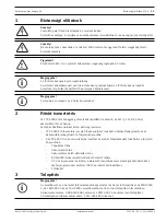
Notice!
Make sure that the temperature sensor of the power supply bracket is connected.
i
Notice!
Only use one battery pair which can be connected either to terminal BAT1 or terminal BAT2 of
the battery controller module.
See first graphics page for illustration of components.
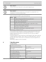
Position
Description
1
PMF 0002 A Power supply housing medium for frame mounting*
2
BCM-0000-B Battery controller module
3
FMH 0000 A Mounting frame medium
4
PRS-0000-C Panel rail short, can hold 2 modules
5
USP 2416 A Universal power supply
6
FPO-5000-PSB2 Power supply bracket*
7
2 battery slots (batteries have to be ordered separately)
*only used in FPP 5000 kit
The panel rail PRS 0002 C is fitted with a BCM‑0000‑B battery controller module. The battery
controller module monitors the power supply and controls the charging of the batteries (e.g. 2
x 12 V / 45 Ah), subject to temperature parameters and set times. The green LED shows that
the unit is operational.
The universal power supply UPS 2416 A is inserted into the power supply bracket, and is
immediately operational via the pre-wired plug-and-socket connections. It is protected against
excess voltage and reversed polarity. The output voltage is monitored and controlled
externally. The output FAULT signals that a malfunction has occurred.
The power supply bracket has a temperature sensor.
4
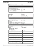
Technical data
FPP-5000 Electrical
AC mains:
Input voltage range (nominal)
110 - 240 V AC
Input voltage
(VdS-approved according to EN54)
230 V AC + 10% / -15%
Input frequency range
50 Hz to 60 Hz
Power source (EN 62368-1)
PS 3
Electrical source (EN 62368-1)
ES 3
Terminals 24 V+/- ①, 24 V+/- ②:
Output voltage (min-max)
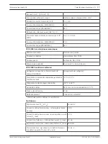
20.4 - 30 V battery-buffered


