background image

6 720 645 347 (2010/09)

6

 | 

Information about this documentation

Information about this documentation

Guide to instructions

If you ...

... are looking for the safety instructions and 
an explanation of the symbols, refer to 

chapter 1

.

... are looking for a summary of the design and 
function of the FR 100 heating controller, 
refer to 

chapter 2

You will also find the specification there.

... are a HEATING ENGINEER and want to know 
how to install, electrically connect and 
commission this accessory, refer to 

chapters 3

 and 

4

.

... want to know how to operate and program 
this accessory, refer to 

chapters 5

,

6

 and

13

There you will also find summaries of the 
factory settings and setting ranges for the 
menus. There are also tables for making a note 
of your settings.

... want to view information about the 
operating condition of the heating system, 
refer to 

chapter 7

.

... are a HEATING CONTRACTOR and want to 
make expert settings or view system 
information, refer to 

chapter 8

. There you will 

also find summaries of the factory settings 
and setting ranges for the menus. There are 
also tables for making a note of your settings.

... are looking for troubleshooting tables, refer 
to 

chapter 9

.

... are looking for tips on saving energy, refer 
to 

chapter


10.

... are looking for a particular keyword in the 
document, have a look in the 

Keyword index


on the last pages.

Additional documentation for the heating 
contractor (not included in standard pack)

In addition to these instructions supplied with 
the product, the following documents are also 
obtainable:

Spare parts catalogue

Servicing instructions (for troubleshooting 
and checking functions)

These documents can be requested from the 
Bosch Information Service. The contact address 
is printed on the back page of these instructions.

These installation and operating 
instructions contain all details of the 
function and operation of the 
FR 100 and FR 110 heating 
controllers. 

Summary of Contents for FR 100

Page 1: ...Installation and operating instructions Room temperature controller with solar control FR 100 FR 110 6 720 612 481 00 1R 6 720 645 347 2010 09 ...

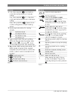
Page 2: ...6 720 645 347 2010 09 2 Overview of controls and symbols Overview of controls and symbols Fig 1 Controls 6 720 617 762 01 1O 3 3 4 1 menu info 1 2 3 5 6 7 8 4 9 12h 15 18 21 24h 3 6 advance advance ...

Page 3: ...r 60 minutes or with combi boilers comfort mode is activated for 30 minutes 5 Open close menu 6 Show settings 7 Delete reset setting 8 Return to next menu up Tab 1 menu info Symbols Current room temperature Flashing segment Current time 13 45 to 14 00 Solid segments time set for operating mode Comfort today or DHW On or 50 C 1 segment 15 min Empty segments time set for operating mode Economy today...

Page 4: ...ging DHW mode time limited 28 5 3 4 Holiday program 28 5 4 Changing the set room temperature 29 5 4 1 Permanently changing the set room temperature 29 5 4 2 Changing the set room temperature for a limited period 29 6 Adjusting the MAIN MENU 30 6 1 Overview and adjustment of the MAIN MENU 30 6 1 1 MAIN MENU Holiday 31 6 1 2 MAIN MENU Heating 32 6 1 3 MAIN MENU Domestic hot water 34 6 1 4 MAIN MENU ...

Page 5: ...onfiguring the solar thermal system 60 8 5 Parameters for solar thermal system 60 8 5 1 Commissioning the solar thermal system 61 8 5 2 Parameters for the standard solar thermal system 61 8 5 3 Parameters for solar optimisation 62 8 6 Fault history 64 8 7 Viewing and entering the customer service address 64 8 8 Viewing system information 64 9 Troubleshooting 65 9 1 Troubleshooting using the displa...

Page 6: ... 7 are a HEATING CONTRACTOR and want to make expert settings or view system information refer to chapter 8 There you will also find summaries of the factory settings and setting ranges for the menus There are also tables for making a note of your settings are looking for troubleshooting tables refer to chapter 9 are looking for tips on saving energy refer to chapter 10 are looking for a particular...

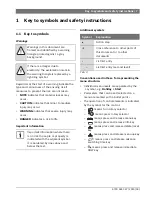
Page 7: ...ation of control elements is indicated by the symbol for the control means turn rotary selector means press rotary selector means press and release menu key means press and release info key means press and release delete reset key means press and release menu up key means press and release advance switching time key means press and release immediate DHW key Warnings in this document are framed and...

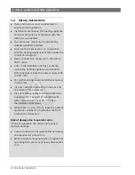
Page 8: ...e heating appliance and all other BUS subscribers from the power supply 220 to 240 V AC B For wall mounting never install this accessory in wet areas B Instruct customers about the functions and operation of the accessory B Risk of scalding during thermal disinfection Supervise short periods of operation with water temperatures over 60 C or fit a thermostatic DHW mixer B When there is a risk of fr...

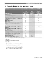
Page 9: ...eating circuit X X X HK 2 HK 10 via FR 10 FR100 X 1 1 with IPM X 1 Time temperature level profile for associated heating circuit X X X Heat up optimisation X X X DHW heating X X DHW heating via heating appliance with DHW heating acc to instantaneous water heater principle X X X 2 2 controlled by the heating appliance DHW heating via DHW cylinder on heating appliance X X X 2 DHW heating via DHW cyl...

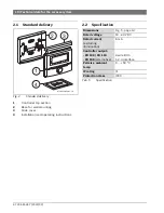
Page 10: ...g 3 Slide cover 4 Installation and operating instructions 2 2 Specification 2 4 1 3 6 720 613 058 01 1R 8 Dimensions Fig 5 page 14 Rated voltage 10 24 V DC Rated current excluding illumination 6 mA Controller output FR 100 FR 110 FR 100 alternative 2 wire BUS 1 2 4 interface Permiss ambient temp 0 50 C IP rating III Protection class IP20 Tab 5 Specification ...

Page 11: ...wo mixed heating circuits Controlling one non mixed heating circuit in the heating system is possible ISM 1 Module for controlling solar DHW heating FR 10 Room temperature controller without heating program to extend the heating system by one additional heating circuit not permissible in Germany 2 4 Cleaning B If required use a damp cloth to wipe the controller casing Never use aggressive or acidi...

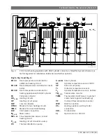
Page 12: ...scheme see technical guides for installation illustration and further options 230 V AC VF HW 6 720 613 058 02 2O MF4 P4 M4 TB4 HK4 HK5 HK10 M MF3 P3 M3 TB3 HK3 M IPM 2 FR 100 FK FR 100 FR 100 FR 100 230 V AC MF2 P2 M2 TB2 HK2 M MF1 P1 M1 TB1 HK1 M IPM 2 HP 230 V AC FR 101 FR 101 FR 101 T1 T2 KW S solar TWM 230 V AC SP ISM 1 ZW WW ...

Page 13: ...water connection M1 10 Mixer motor MF1 10 Flow temperature sensor mixed heating circuit P1 10 Heating circuit circulation pump PE Thermal disinfection pump S solar Solar cylinder SF Cylinder temperature sensor NTC SP Solar circuit pump T1 Collector temperature sensor T2 Cylinder temperature sensor bottom TB1 10 Temperature monitor TWM Thermostatic DHW mixer to protect combi boiler against overheat...

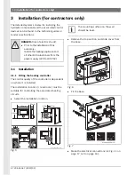
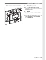
Page 14: ...ad room must be suitable for controlling the associated heating circuits B Select the installation location Fig 5 B Remove the top section and slide cover from the base Fig 6 B Fit the base Fig 7 B Make the electrical connections Æ Fig 11 on page 17 or 9 on page 16 DANGER Risk of electric shock B Prior to the installation of this accessory Isolate the heating appliance and all other BUS subscriber...

Page 15: ...her accessories B Fit accessories according to the legal requirements and the installation instructions supplied with them 3 1 3 Disposal B Dispose of packaging in an environmentally responsible manner B When replacing components dispose of the used components in an environmentally responsible manner 3 2 1 6 720 612 220 06 1R ...

Page 16: ...r stations radio and television set amateur radio stations microwave ovens etc 3 2 1 Connecting the BUS link Permissible lead lengths from the BUS enabled Heatronic 3 to the controller B Connect the controller to a heating appliance with BUS enabled Heatronic 3 Fig 9 Controller connected to BUS enabled Heatronic 3 Fig 10 BUS links connected via branch box A Lead length Cross section 80 m 0 40 mm2 ...

Page 17: ...iance with optional connections for analogue 1 2 4 interface 24 V DC Fig 11 FR 100 connected via the analogue 1 2 4 interface Lead length Cross section 20 m 0 75 mm2 1 50 mm2 30 m 1 00 mm2 1 50 mm2 30 m 1 50 mm2 Tab 7 The third contact enables the controller to recognise that it is not connected via the BUS link but instead via the analogue 1 2 4 interface FR 100 1 2 4 1 2 4 1 2 4 1 2 4 DC 24V 6 7...

Page 18: ...uit only FR 100 with BUS connection If the controller is to control heating circuit HC1 and DHW heating Identification CH circuit select code 1 with and confirm with If the controller is to control heating circuit HC2 10 Identification CH circuit with select a code between 2 and 10and confirm with 7 During commissioning automatic system configuration starts immediately after entry of the date and ...

Page 19: ...ircuits e g heating circuit 1 is for the radiator heating system and heating circuit 2 for the underfloor heating system Explain to the user how to operate the system on a day to day basis e g time operating modes for the heating circuits DHW temperature time programs for heating circuits and DHW Explain how to use the thermal disinfection function and the associated risk of scalding Hand all docu...

Page 20: ...es in chapters 6 1 7 and 8 1 show the entire menu structure They also provide details of the setting ranges and factory settings for all adjustable parameters More information on the menu points can be found in sections 6 2 to 6 5 for the user level and sections 8 2 to 8 8 for the contractor level The description of a menu points starts with its menu path That shows you how to reach the menu point...

Page 21: ...e is specified for each switching time The specified operating mode applies until changed by the next switching time Heating programs Heating programs control central heating operation There are three modes for heating operation Comfort Economy Frost frost protection or Individual temperature levels 5 C to 30 C in 1 C increments For each of these operating modes there is a set room temperature sto...

Page 22: ...rity the menu is subdivided into three sections MAIN MENU INFO INSTALLER SETTINGS Each section can be accessed by its own button The entire menu structure is shown in tabular form in chapters 6 1 7 and 8 1 To navigate through the menu Press to open MAIN MENU From any point within the MAIN MENU press to go back to the standard display Press to open the INFO menu From any point within the INFO menu ...

Page 23: ...ching point The unit is supplied with programs for heating and DHW already stored It may also be that your heating installer has adjusted the programs to suit your requirements lifestyle Changing moving or deleting a single switching point B Open flap The standard display continues to be shown B Press The display lighting switches on and the main menu is displayed The example below shows all the s...

Page 24: ...rent menu title EDIT PROGRAMME A B Turn until the required day or group of days is highlighted e g Monday The segment ring always shows you the heating program if you highlight just one specific day e g Monday or if on a group of days all switching times are identical for every day in that group e g all switching times for Mon Fri are identical B Press to confirm the menu point Monday The next sub...

Page 25: ... now change more switching times and operating modes in the same way or finish programming and return to the standard display by pressing Using groups of days when programming In many cases you may want to programme the same switching times for several days of the week say for all working days Equally you may also want a different program for just one of those days Using the groups of days when pr...

Page 26: ...tored in the memory Æ chapter 13 on page 77 Overwrite one of your own heating programs A to F as follows B Call up the relevant program e g menu Heating Programme Edit C Programme C or menu Domestic hot water DHW programme Edit B Turn until menu point Reset factory settings is highlighted B Press The program has now been reset to the factory settings Resetting all settings for heating contractors ...

Page 27: ...he specified room temperature set for the next switching point was to become active This function is only available when mode is switched on B Briefly press to bring forward the next switching time and the associated operating mode Comfort Economy Frost for the selected heating circuit to the current time The segment ring and header show the modified settings or B Press and hold and simultaneously...

Page 28: ...isplay lighting switches on and the main menu is displayed B Press The holiday menu is selected and the header shows the current menu title in this case Holiday B Press The display changes to the holiday menu and Start is selected Now you can enter the date on which you want the holiday program to start Enter the year month and day one after the other and confirm each entry with B Turn until End i...

Page 29: ...e as possible to the set room temperature subject to the set operating mode in mode subject to the active heating program and the time If you wish to permanently alter the set room temperature proceed as follows B Call up menu Heating Parameter Heating levels B Set the temperature for each operating mode Æ chapter 6 2 2 page 40 5 4 2 Changing the set room temperature for a limited period B Set the...

Page 30: ...rogramme submenus Edit and View are on the same level An overview of the factory settings column 2 e g for resetting individual menu points to the default An overview of the setting ranges of the individual menu points column 3 Space for making a note of your personal settings column 4 References to the detailed descriptions of the individual menu points column 5 The menu points are only shown if ...

Page 31: ... increments of one day month year 28 End Start date 31 12 2099 in increments of one day month year Heating Frost Frost Economy Comfort Auto Domestic hot water Off1 Off Auto On1 15 C2 15 C 60 C Auto DHW circulation pump Off Off Auto On Thermal disinfection Off Off On 1 DHW heating with FR 100 FR 110 and combi boiler or with FR 100 via DHW cylinder 2 DHW heating with FR 110 via DHW cylinder ...

Page 32: ... A C Programme C Copy from preset programme No No A Programme A C Programme C program title can be changed AM weekday worker PM weekday worker Full weekday worker AM PM weekday worker Home all day Home all day early Home all day late Senior citizens All days Æ Tables from page 77 Æ Tables from page 79 Æ Tables from page 81 P1 P2 P6 Mon Fri P1 P2 P6 Sat Sun P1 P2 P6 Monday Tuesday Sunday P1 P2 P6 R...

Page 33: ...ted in Edit menu e g Programme D Changing the program title View A Programme A F Programme F AM weekday worker PM weekday worker Full weekday worker AM PM weekday worker Home all day Home all day early Home all day late Senior citizens All days All days Mon Fri Sat Sun Monday Tuesday Sunday Parameter 40 Heating levels Comfort 21 0 C 7 0 C 30 0 C higher than Economy C Economy 15 0 C 6 0 C 29 C high...

Page 34: ...gramme2 Edit All days Æ Table on page 83 Æ Table on page 83 Æ Table on page 83 P1 P2 P6 Mon Fri P1 P2 P6 Sat Sun P1 P2 P6 Monday Tuesday Sunday P1 P2 P6 Reset factory settings No No Yes View All days Mon Fri Sat Sun Monday Tuesday Sunday DHW circ pump prog 2 3 46 Edit All days Æ Table on page 84 Æ Table on page 84 Æ Table on page 84 P1 P2 P6 Mon Fri P1 P2 P6 Sat Sun P1 P2 P6 Monday Tuesday Sunday ...

Page 35: ...rc pump cycles 4 h 1 h 7 h hour Thermal disinfection 48 Operating mode Manual Manual Auto Operating status Not running Not running Start now Running Running Stop Time 01 00 h 00 00 h 23 45 h hours Time interval 7 days 1 day 30 days days 1 Only FR 110 or FR 100 with code 1 2 Only with Separate programmes 3 Only with FR 110 Menu structure Domestic hot water 1 Factory setting Setting range Personal s...

Page 36: ...SM or cylinder Date Date Required room temp Without ISM with cylinder Cylinder temperature Cylinder temperature Date Required room temp With ISM and cylinder Solar pump status Solar pump status Solar yield Required room temp Date Cylinder temperature With ISM but without cylinder Solar pump status Solar pump status Solar yield Required room temp Date Key lock Off Off On 49 Language English English...

Page 37: ...for heating programs A to C An individual time temperature profile with user defined temperatures can be created for the heating programs D to F Fig 14 Example time temperature profile with user defined temperatures for heating programs D to F Menu Heating Programme Use this menu to create change or activate a heating program for each associated heating circuit The heating programs are only active...

Page 38: ...activate switching times that are not required by deleting them Skip switching times and operating modes that are not to be changed with or For menu structure and setting ranges Æ page 32 Menu Heating Programme Edit D Programme D F Programme F All days Use this menu to set identical times for every day for the heating program of your choice P1 P2 P6 Maximum of six switching times per day with temp...

Page 39: ...P6 For explanation see A Programme A above C Programme C All days For menu structure and setting ranges Æ page 32 Menu Heating Programme Edit D Programme D F Programme F Monday Tuesday Sunday Use this menu to set your custom heating program for individual days e g Thursday start every Thursday at the same time with the selected operating mode P1 P2 P6 For description see under D Programme D above ...

Page 40: ...imum required temperature e g when the home is empty or everyone is in bed and it is OK for the house to cool down Consider any pets and plants For menu structure and setting ranges Æ page 32 6 3 DHW program Main menu Domestic hot water Display of the segments for heating programs C D and F individual temperature profiles is also dependent on the settings made here The DHW program is only availabl...

Page 41: ...elected DHW temperature starts Cylinder temp at heating level Comf 1 This setting remains active for as long as the heating circuit stays in Comfort mode If the heating circuit is in Economy mode then the cylinder will be held at the temperature selected under Cylinder temp at heating level Eco1 If the heating circuit is in Frost mode then frost protection is also applied to the cylinder 15 C fixe...

Page 42: ... a result energy is saved In eco mode the hot tap has to be run for a short while before the water becomes hot Empty segments on the display indicate the period for which this operating mode is active The shortest switching interval is 15 minutes 1 segment Deactivate switching times that are not required by deleting them For menu structure and setting ranges Æ page 34 Menu Domestic hot water DHW p...

Page 43: ...de is active Off Cylinder heating blocked Empty segments on the display indicate the period for which this operating mode is active The shortest switching interval is 15 minutes 1 segment Deactivate switching times that are not required by deleting them For menu structure and setting ranges Æ page 34 Menu Domestic hot water DHW programme Edit Mon Fri Use this menu to change the DHW program with id...

Page 44: ...t water DHW programme Edit All days Use this menu to set identical times for each day for the DHW program P1 P2 P6 Maximum of six switching times per day with individual temperature levels 15 C to 60 C If the temperature measured in the DHW cylinder is below the set temperature the cylinder is reheated Once the set temperature is reached or exceeded cylinder reheating is stopped The shortest switc...

Page 45: ...es Æ page 34 Menu Domestic hot water DHW programme Edit Monday Tuesday Sunday Use this menu to set the DHW program differently for individual days P1 P2 P6 For description see All days above For menu structure and setting ranges Æ page 34 Menu Domestic hot water DHW programme View B Shows switching times and associated temperatures for All days Mon Fri Sat Sun or the individual day of the week as ...

Page 46: ...riod for which this operating mode is active The shortest switching interval is 15 minutes 1 segment Deactivate switching times that are not required by deleting them For menu structure and setting ranges Æ page 34 Menu Domestic hot water DHW circ pump prog Edit Mon Fri Use this menu to change the DHW program with identical times for Monday to Friday P1 P2 P6 For description see All days above For...

Page 47: ...is not to be switched off during cylinder heating e g for buildings with limited insulation and low outside temperatures Priority The heating is switched off during DHW heating The pumps stop and the mixers are closed Conditional priority During DHW heating the mixed heating circuits carry on heating the pumps run and the mixers regulate to the required temperature The non mixed heating circuit is...

Page 48: ...ion in progress Thermal disinfection can be terminated by selecting Stop If Solar sys option E Thermal disinfection is switched on Æ chapter 8 4 on page 60 and thermal disinfection is terminated by selecting Stop a fault is indicated for 5 minutes if the disinfection temperature in the solar cylinder has not been reached fault 54 Æ chapter 9 1 from page 65 Time Start time for automatic thermal dis...

Page 49: ...MM YYYY or MM DD YYYY as date display format D digit for day M digit for month Y digit for year Display contrast Sets display contrast to between 25 and 75 Information at top of display Sets the required information to be shown on the top line of the standard display For menu structure and setting ranges Æ page 36 6 4 3 Key lock For menu structure and setting ranges Æ page 36 Key lock Use this men...

Page 50: ...e heating appliance will then not be required to produce as much heat and will use less gas For more information for heating contractors Æ chapter 8 5 3 on page 62 Optimizing influence DHW Maximum reduction of set DHW temperature by effect of solar thermal system Example Set DHW temperature 60 C Optimizing influence DHW 15 K Set DHW temperature for heating appliance 60 C 15 K Provided there is suf...

Page 51: ... items column 3 The menu points are only shown if the system components are installed and or active Some menu points are not shown because they are switched off by a setting for another menu point Menu structure INFO Display example Description Boiler Heating mode possible Yes No Shows whether heating appliance is ready for operation Current CH flow temperature 55 0 C Current heating appliance flo...

Page 52: ...tured in the assigned heating circuit Heating pump On Off Switching state of the heating circuit pump in the assigned heating circuit Current mixer setting 85 open Current opening state of mixer in the assigned heating circuit Domestic hot water Operating mode Immediate DHW Auto On Auto Off Holiday Auto Holiday On Holiday Off Current operating mode or special mode for DHW with combi boiler Immedia...

Page 53: ...Status of thermal disinfection pump PE Solar optimisation3 Menu for solar assisted optimisation of conventional heating system Solar yield in last hour 120 Wh Solar energy yield in the last hour a figure is only shown if correct parameters have been set on the solar optimisation menu Æ chapter 8 5 3 on page 62 Solar yield today 2 38 kWh Solar energy yield for the current day Solar yield overall 48...

Page 54: ...ion are on the same level An overview of the factory settings column 2 e g for the purposes of resetting individual menu points to their factory setting An overview of the adjustment ranges of the individual menu points column 3 Space for making a note of your personal settings column 4 For locating detailed descriptions regarding the individual menu points column 5 The INSTALLER SETTINGS menu is ...

Page 55: ... 10 DHW circulation pump2 No No Present CH system configuration Unmixed without IPM Unmixed without IPM Unmixed with IPM Mixed Identification CH circuit 1 1 10 only FR 100 with BUS connection ISM 1 No No Present ISM 2 No No Present 1 Only FR 110 or FR 100 with code 1 2 Only with FR 110 Menu structure Heating parameters Factory setting Setting range Personal setting Description from page Calibrate ...

Page 56: ...100 C 140 C C SP Collector grp 1 pump mode Auto Auto Manual On Manual Off PE Therm disinfect pump mode Auto Auto Manual On Manual Off 60 Solar optimisation 62 Collector group 1 area 0 0 m2 0 0 m2 150 0 m2 m2 Collector group 1 type Flat plate collector Flat plate collector Vac tube collector Climate zone 90 0 255 Optimizing influence DHW 0 K 0 K function off 20 K K Run solar system No No Yes 61 Men...

Page 57: ... from page Installation date 22 10 2010 activated on commissioning 64 Boiler part number 7 777 777 777 data from heating appliance Boiler date of manufacture 27 06 2010 data from heating appliance Controller part number and model 7 777 777 777 FR 100 fixed factory setting Controller date of manufacture 27 06 2010 fixed factory setting Controller software version JF11 12 fixed factory setting ...

Page 58: ...s menu point is only active if a DHW circulation pump has been installed in the DHW system only for FR 110 Identification CH circuit for the selection of the associated heating circuit 1 10 only FR 100 When commissioning a heating system proceed as follows B Code all BUS subscribers in accordance with their function e g IPM 1 for heating circuit 1 etc B Start automatic configuration B Check the ot...

Page 59: ...t 80 Set a higher factor to increase the influence on the heat demand The selected room temperature is reached quickly with a tendency to overshoot Heat up optimisation No The heating program contains only switching times for the assigned heating circuit Yes The heating program contains times for the required room temperatures The controller shifts the switching times for the heating automatically...

Page 60: ...ermal disinfection Auto Automatically controlled operation according to the set parameters Manual On Switches the pump permanently on e g for function test when commissioning Manual Off Switches the pump permanently off e g for servicing work on the pump without having to interrupt heating operation For menu structure and setting ranges Æ page 56 The heating system s solar thermal system has to be...

Page 61: ...tched on SP OFF temperature difference Use this menu point to set the stop temperature differential for the solar circuit pump SP If the differential between collector temperature T1 and the solar cylinder temperature T2 drops below the set value the solar circuit pump SP will be switched off T2 Max solar cylinder temperature For a detailed description of T2 Max solar cylinder temperature Æ page 5...

Page 62: ...ector group 1 Collector group 1 type Use this menu point to set the installed collector type for collector group 1 Climate zone Use this menu point to set the climate zone number for the geographical region in which the system is located Find the location of your system on the climate zones map Æ Fig 16 and enter the climate zone number If your location is not shown on the map leave the number as ...

Page 63: ...6 720 645 347 2010 09 Menu settings INSTALLER SETTINGS for contractors only 63 Fig 16 Map with the climate zones 6 720 645 340 20 1O ...

Page 64: ...me The heating contractor can enter the address of the heating contractor responsible for customer service here For menu structure and adjustment range Æ page 56 8 8 Viewing system information Contractor level System info Shows a variety of system information Installation date automatically activated on commissioning Boiler part number fixed setting from heating appliance Boiler date of manufactur...

Page 65: ...r 2 BUS subscriber which detected the fault and reported it to the controller 3 Description of fault 4 Code or additional information about fault The current fault is indicated on the controller B Identify the BUS subscriber affected by the current fault The fault can only be rectified on the BUS subscriber from which the fault originates For heating contractors B Rectify the fault in accordance w...

Page 66: ...ernal fault Some parameters reset to factory settings due to EEPROM problem 205 Some parameters reset to default Check parameter settings and readjust as necessary Identify faulty controller and replace Fault 02 Internal fault FR110 can no longer control the CH system 255 FR 100 FR 110 can no longer control the heating system Identify faulty controller and replace Fault 03 Room temp sensor faulty ...

Page 67: ... system configuration for DHW or start automatic system configuration 157 BUS subscriber changed or replaced Check system configuration for DHW heating or start automatic system configuration Fault 13 System configuration BUS device changed or replaced Check system configuration for heating circuit x and connections on IPM for heating circuit x 159 BUS subscriber changed or replaced Check system c...

Page 68: ...e sensor and insert a coding plug if necessary Fault 34 Temperature sensors connected and mode of operation do not match 23 Temperature sensors connected to the IPM and the associated operating mode do not match Check temperature sensors and associated operating mode and adjust if necessary Fault 40 Temperature sensor T1 on collector group 1 faulty 101 Short circuit on the sensor lead T1 Check tem...

Page 69: ... sensor T1 close to collector array outlet Fault 54 Temperature for thermal disinfection not reached in solar cylinder 145 Maximum temperature for solar cylinder too low Set higher maximum temperature for solar cylinder Æ Limiting cylinder temperature page 50 Pump rate of disinfection pump PE too low Set higher pump speed on disinfection pump PE or if possible open flow restrictor further Thermal ...

Page 70: ...orrectly e g increase reduce pump speed or if necessary further open or close valve to the solar pumping station Guide figure 20 40 kg m2 of collector area per hour Check setting for collector area type and climate zone on Solar optimisation menu 202 Mass flow rate in solar thermal system for collector group 1 is too low Information displayed Æ Items 1 3 and 4 in Fig 17 Text Code Cause Remedy by c...

Page 71: ...ature rises instead of falling Time incorrectly set Check time setting Room temperature too high during Economy and or Frost mode The building retains a lot of heat Set an earlier switching time for Economy and or Frost Incorrect or nocontrol BUS connection of BUS subscribers faulty Ask your heating contractor to check the BUS connection against the connection diagram and correct if required Contr...

Page 72: ...ting If the fault persists B Call an authorised contractor or the customer service department and inform them of the fault quoting the appliance details from type plate inside flap Appliance details Type Part number Date of manufacture FD ...

Page 73: ...umption than if an even heat supply is applied Good thermal insulation of the building the set temperature for Economy is never reached Nevertheless energy is being saved as the heating system stays off In that case set the switching point for Economy to an earlier time Don t keep windows slightly open for ventilation This leads to a constant extraction of heat from the room without noticeably imp...

Page 74: ...y or Comfort In that case bring the time forward by an appropriate amount Only charge the DHW cylinder outside the heat up period e g 30 minutes after the heating start time If the radiators become unpleasantly hot the maximum flow temperature should be reduced accordingly on the heating appliance Solar optimisation Activate the Optimizing influence DHW on the FR 110 by setting a figure of between...

Page 75: ...he best possible technology and materials for protecting the environment taking account of economic considerations Packaging Where packaging is concerned we participate in country specific recycling processes that ensure optimum recycling All packaging materials are environmentally compatible and can be recycled Used appliances Used appliances contain materials that should be recycled The relevant...

Page 76: ...mixed FR 10 FR 100 Code 5 type IPM 1 IPM 2 8 mixed non mixed FR 10 FR 100 Code 6 type IPM 1 IPM 2 9 mixed non mixed FR 10 FR 100 Code 7 type IPM 1 IPM 2 10 mixed non mixed FR 10 FR 100 Code 8 type IPM 1 IPM 2 Solar thermal system Code 9 type IPM 1 IPM 2 Solar options E Code 10 type IPM 1 IPM 2 The following work has been carried out Switch off Auto switch between GMT BST Water circulation systems ...

Page 77: ...ed pre defined heating programs for copying P1 P2 P3 P4 P5 P6 AM weekday worker Mo Th 06 00 08 00 12 00 22 00 Fr 06 00 08 00 12 00 23 30 Sa 07 00 23 30 Su 08 00 22 00 PM weekday worker Mo Th 07 00 12 00 17 00 22 00 Fr 07 00 12 00 17 00 23 30 Sa 07 00 23 30 Su 08 00 22 00 Full weekday worker Mo Th 06 00 08 00 17 00 22 00 Fr 06 00 08 00 17 00 23 30 Sa 07 00 23 30 Su 08 00 22 00 AM PM weekday worker ...

Page 78: ...0 Fr 06 00 23 30 Sa 07 00 23 30 Su 08 00 22 00 Home all day early Mo Th 04 00 22 00 Fr 04 00 23 00 Sa 07 00 23 00 Su 07 00 22 00 Home all day late Mo Th 06 00 23 30 Fr 06 00 23 30 Sa 07 00 23 30 Su 08 00 23 30 Senior citizens Mo Th 07 00 23 00 Fr 07 00 23 00 Sa 07 00 23 00 Su 07 00 23 00 P1 P2 P3 P4 P5 P6 ...

Page 79: ...y 06 00 22 00 Thursday 06 00 22 00 Friday 06 00 23 30 Saturday 07 00 23 30 Sunday 08 00 22 00 Program B All days Mon Fri Sat Sun Monday 06 00 08 00 17 00 22 00 Tuesday 06 00 08 00 17 00 22 00 Wednesday 06 00 08 00 17 00 22 00 Thursday 06 00 08 00 17 00 22 00 Friday 06 00 08 00 17 00 23 30 Saturday 07 00 23 30 Sunday 08 00 22 00 Program C All days 07 00 23 00 Mon Fri Sat Sun Monday Tuesday Wednesda...

Page 80: ...day 21 07 00 5 23 30 Sunday 21 08 00 5 22 00 Program E All days Mon Fri Sat Sun Monday 21 06 00 15 08 00 21 17 00 5 22 00 Tuesday 21 06 00 15 08 00 21 17 00 5 22 00 Wednesday 21 06 00 15 08 00 21 17 00 5 22 00 Thursday 21 06 00 15 08 00 21 17 00 5 22 00 Friday 21 06 00 15 08 00 21 17 00 5 23 30 Saturday 21 07 00 5 23 30 Sunday 21 08 00 5 22 00 Program F All days 21 07 00 15 23 00 Mon Fri Sat Sun M...

Page 81: ...t Sun Monday Tuesday Wednesday Thursday Friday Saturday Sunday Program location B title ________________________ assigned to heating circuit ____ All days Mon Fri Sat Sun Monday Tuesday Wednesday Thursday Friday Saturday Sunday Program location C title ________________________ assigned to heating circuit ____ All days Mon Fri Sat Sun Monday Tuesday Wednesday Thursday Friday Saturday Sunday ...

Page 82: ...t Sun Monday Tuesday Wednesday Thursday Friday Saturday Sunday Program location E title ________________________ assigned to heating circuit ____ All days Mon Fri Sat Sun Monday Tuesday Wednesday Thursday Friday Saturday Sunday Program location F title ________________________ assigned to heating circuit ____ All days Mon Fri Sat Sun Monday Tuesday Wednesday Thursday Friday Saturday Sunday ...

Page 83: ...re level only for FR 110 with DHW cylinder On Off for combi boiler and FR 100 with DHW cylinder on the heating appliance C1 C1 C1 C1 C1 Factory settings Mo Th 60 On 05 00 15 Off 23 00 Fr 60 On 05 00 15 Off 23 00 Sa 60 On 06 00 15 Off 23 00 Su 60 On 07 00 15 Off 23 00 Personal settings for Domestic hot water All days Mon Fri Sat Sun Monday Tuesday Wednesday Thursday Friday Saturday Sunday ...

Page 84: ...stic hot water circulation program is described in chapter 6 3 on page 40 P1 P2 P3 P4 P5 P6 On Off On Off On Off On Off On Off On Off Factory settings Mo Th On 06 00 Off 23 00 Fr On 06 00 Off 23 00 Sa On 07 00 Off 23 00 Su On 08 00 Off 23 00 Personal settings All days Mon Fri Sat Sun Monday Tuesday Wednesday Thursday Friday Saturday Sunday ...

Page 85: ...ermal system parameters 56 60 System configuration 55 58 System configuration Menu 58 System faults 56 64 System info 57 64 Contrast 49 Control quality 14 Controller messages 65 Controls 3 Cooler Domestic hot water 40 Customer service address 56 64 D DHW circulation 46 Dimensions 14 Display Contrast 49 Standard display 49 Display formats 49 Disposal 15 75 Domestic hot water program 34 40 E Electri...

Page 86: ...6 50 Menu structure 31 51 55 Mixed heating circuit 11 47 N Night mode economy 40 Non mixed heating circuit 47 O Operation 20 Changing DHW mode 28 Changing room temperature 29 40 Changing the operating mode for heating 27 Setting heating temperature 40 Option E Thermal disinfection of the solar cylinder 60 P Packaging 15 75 Power module IPM 2 accessory 13 Power reserve Mains power failure 9 Product...

Page 87: ...40 Setting language 49 Setting the date 49 Setting the time 49 Solar circuit pump SP 61 Solar module for central heating backup ISM 2 accessory 13 Solar optimisation 50 Solar program 36 50 Solar radiation 73 Standard display 49 Standard package 10 Standard solar thermal system 61 Stove 73 Switching off summer wintertime 49 Symbols 3 System configuration 58 Automatic 18 58 System faults 56 64 Syste...

Page 88: ...ralia Robert Bosch Australia Pty Ltd 1555 Centre Rd Clayton VIC 3168 Phone 1300 30 70 37 Fax 1300 30 70 38 www bosch com au hotwater New Zealand Phone 0800 4 Bosch or 08 543 352 www bosch co nz 067206453474 ...

Reviews: