Applications Manual Bosch Greenstar
| 67
Bosch Thermotechnology Corp.
Data subject to change
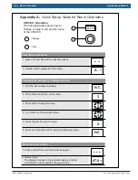
Appendix A:
Quick Set-up Guide for Room Controllers
CRC100 control set-up:
For single zone application where CRC100 is connected directly to the boiler:
Ź
Set A.1 value to “CO”
Note: Please consult the installation manual for a complete overview of the controller settings and proper installation. The
following guide is not a substitute for the installation manual.
For a multi- zone application where CRC100 is connected to a CZM100:
Ź
Set H.C on each CRC100 to the appropriate zone number (1 thru 8)
CRC200 control set-up:
For single zone application where the CRC200 is connected directly to the boiler:
Ź
Set DHW to “yes – pr. pump” if indirect tank is connected to the system
Ź
Set “Heat System” to “High Temp” or “Low Temp” depending upon system requirement
Ź
Set “Max Supply Temp” to appropriate maximum temperature for the system
For a multi- zone application where CRC200 is connected to a CZM100:
Ź
Set HC on each CRC200 to the appropriate zone number (1 thru 8)
For CRC200 located in Zone #1:
Ź
Set DHW to “yes – pr. pump” if indirect tank is connected to the system
Ź
Set “Heat System” to “High Temp” or “Low Temp” depending upon zone requirement
Ź
Set “Max Supply Temp” to appropriate maximum temperature for the zone
For CRC200 located in zones 2 thru 8:
Ź
Set “Heat System” to “High Temp” or “Low Temp” depending upon zone requirement
Ź
Set “Max supply Temp” to appropriate maximum temperature for the zone
Coding and Connection to…..
CZM100 #1
CZM100 #2
CZM100 #3
Heating
Zone
Number
Pump
contacts
1
2
3
4
5
6
7
8
1
1
1
2
2
2
3
3
-
-
-
-
-
-
-
-
-
-
-
-
-
-
-
PZ1
-
-
PZ2
PZ3
PZ1
PZ2
PZ3
PZ1
PZ2
Coding and Connection to…..
CZM100 #1
CZM100 #2
CZM100 #3
Heating
Zone
Number
Zone
Valve
Contacts
1
2
3
4
5
6
7
8
4
4
4
5
5
5
6
6
-
-
-
-
-
-
-
-
-
-
-
-
-
-
VZ1
-
-
VZ2
VZ3
VZ1
VZ2
VZ3
VZ1
VZ2
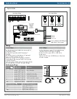
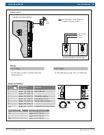
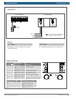
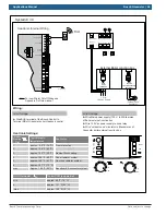
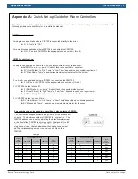
Zone number and corresponding pump/Zone valve output on CZM100:
The CZM100 can support systems using Pumps or Zone valves but
not both. The maximum number of CZM100 in a system is 3. The
CZM100 address can be set by adjusting the potentiometer screw
on the front of the CZM100 (see image right). Address #1 thru #3
is for systems using pumps. Address #4 thru #6 is for systems
using zone valves. Charts below show the heating zone number
and the corresponding pump or zone valve contacts on the
CZM100.
Pumps
Summary of Contents for FS 100
Page 2: ...2 Bosch Greenstar Applications Manual Bosch Thermotechnology Corp Data subject to change ...
Page 73: ...Applications Manual Bosch Greenstar 73 Bosch Thermotechnology Corp Data subject to change ...
Page 74: ...74 Bosch Greenstar Applications Manual Bosch Thermotechnology Corp Data subject to change ...
Page 75: ...Applications Manual Bosch Greenstar 75 Bosch Thermotechnology Corp Data subject to change ...

