18
| English
Note:
The battery is supplied partially charged. To ensure
full battery capacity, completely charge the battery in the
battery charger before using for the first time.
The lithium-ion battery can be charged at any time without
reducing its service life. Interrupting the charging procedure
does not damage the battery.
The “Electronic Cell Protection (ECP)” protects the lithium-
ion battery against deep discharging. When the battery is
empty, the product is switched off by means of a protective
circuit: The pump no longer operates.
Observe the notes for disposal of the battery.
Charging Procedure (see figure H)
The charging procedure starts as soon as the mains plug of
the charger is plugged into a socket outlet and the battery
(22)
is inserted onto the charger
(23)
.
Due to the intelligent charging method, the charging condi-
tion of the battery is automatically detected and the battery
is charged with the optimum charging current, depending on
battery temperature and voltage.
This gives longer life to the battery and always leaves it fully
charged when kept in the charger for storage.
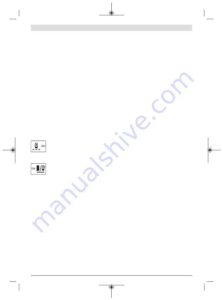
Meaning of the Indication Elements (AL 1810)
Flashing battery charge indicator
The charging process is indicated by the
flash-
ing
of the battery charge indicator .
Solid light on battery charge indicator
A
solid light
on the battery charge indicator
signals that the battery is fully charged or that
the temperature of the battery is not within the
permitted charging temperature range, and
can therefore not be charged. The battery is charged as soon
as the allowable charging temperature range is reached.
When the battery is not inserted, a
solid light
on the battery
charge indicator signals that the mains plug is inserted in the
plug socket and that the charger is ready for operation.
Assembly
Fastening the Wall Attachment/Water Tank
Attachment (see figure B)
Fasten the wall attachment
(10)
next to the water tank. Note
that the distance to the water tank is limited due to the con-
necting cable length.
The distance to the water tank plus the water tank height
may not be larger than the length of the connecting cable.
When mounting the wall attachment to the wall, use the
guide holes to mark the position of the screws.
If wall mounting is not possible, the provided water tank at-
tachment
(8)
can be attached directly to the rim of the water
tank.
NOTE:
The battery control unit is switched off via a thermal
switch at increased temperature. The attachment for the
battery control unit should therefore be mounted in a
shaded position.
Inserting/Removing the Battery Control Unit
(see figure C)
In the case of wall attachment take out the securing
screw
(9)
from the attachment, attach the battery control
unit
(6)
from above into the wall attachment and secure it at
the bottom with the clip and securing screw
(9)
.
In case of water tank attachment just clip the battery control
unit on the attachment.
Determining the required length of cable and
connecting hose (see figure D)
Note: The pump needs to be positioned 50 mm above the
base of the tank, clear of any sediment that might damage
the pump.
Measure the height H and the diameter D of the water tank
as well as the distance E from the rim of the tank to the bat-
tery control box.
The length L
1
of the cable calculates as follows:
H + D + E – 250 mm
The length L
2
of the connecting hose calculates as follows:
H – 130 mm
Wrapping the cable and cutting the connecting
hose (see figure E)
Wrap the excess cable around the pump
(18)
and secure us-
ing the provided cable clamp
(16)
.
Release the anti-siphon connector
(12)
with hose attached
from the clamp on the hose guide
(11)
.
Cut the connecting hose to length L
2
and re-attach the anti-
siphon connector
(12)
on the remaining connecting hose.
Return the anti-siphon connector
(12)
with hose into the
clamp on the hose guide
(11)
.
You can leave the connecting hose uncut and let the hose
protrude. Please note that for the anti-siphon connector to
function the anti-siphon connector needs to be placed to its
original position in the hose guide.
Connecting the hose and cable (see figure F)
Take the 2-pin plug connector
(21)
on the power cable and
align it with the junction point on the battery control unit and
insert until it is firmly seated.
Screw the union nut onto the cable connection to secure the
plug and prevent water from entering.
Attach the universal connector
(14)
on the connecting
hose
(13)
to the hose connection
(19)
on the pump.
Placing the pump into the tank and connecting a
garden hose (see figure G)
With the connecting hose attached lower the pump into the
tank.
F 016 L81 984 | (07.11.2019)
Bosch Power Tools
Summary of Contents for GardenPump 18
Page 302: ...302 5 10 15 5 10 15 B C 10 9 6 8 9 F 016 L81 984 07 11 2019 Bosch Power Tools ...
Page 304: ...304 5 10 15 50 mm G 19 14 21 F 13 12 F 016 L81 984 07 11 2019 Bosch Power Tools ...
Page 307: ... 307 5 10 15 5 10 15 5 10 15 L M 7 6 17 18 22 N Bosch Power Tools F 016 L81 984 07 11 2019 ...
Page 308: ...308 F 016 800 599 F 016 800 598 O F 016 L81 984 07 11 2019 Bosch Power Tools ...


