background image

 English | 

15

Bosch Power Tools

1 609 92A 27R | (4.7.16)

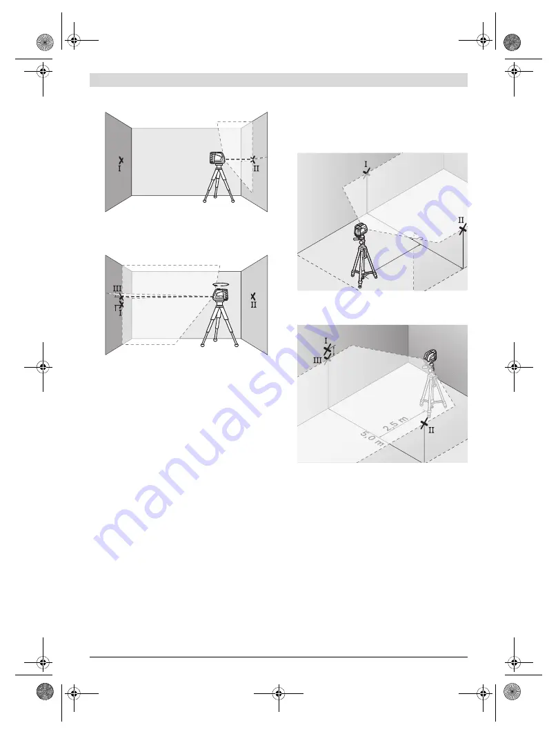
– Without turning the measuring tool, position it close to 

wall B. Switch the measuring tool on and allow it to level in.

– Align the height of the measuring tool (using a tripod or by 

underlaying, if required) in such a manner that the cross 
point of the laser lines is projected against the previously 
marked point

II

 on the wall B.

– Without changing the height, turn around the measuring 

tool by 180°. Direct it against the wall A in such a manner 
that the vertical laser line runs through the already marked 
point

I

. Allow the measuring tool to level in and mark the 

cross point of the laser lines on the wall A (point

III

).

– The  difference 

d

 of both marked points

I

 and 

III

 on wall A 

indicates the actual height deviation of the measuring tool.

The maximum permitted deviation d

max

 is calculated as fol-

lows:
d

max

= double distance of the walls x 0.3 mm/m

Example: With a 5 metre distance between the walls, the max-
imum deviation must not exceed
d

max

= 2 x 5 m x 0.3 mm/m = 3 mm.  Thus,  the  marks  must  not 

be more than 3 mm apart.

Checking the Levelling Accuracy of the Horizontal Line

For the check, a free surface of approx. 5 x 5 metres is re-
quired.

– Set up the measuring tool on a firm, level surface between 

both walls A and B. Allow the measuring tool to level in 
while in horizontal operation.

– At a distance of 2.5 metres from the measuring tool, mark 

the centre of the laser line (point

I

 on wall A and point

II

 on 

wall B) on both walls.

– Set up the measuring tool 5 metres away turned by 180° 

and allow it to level in. 

– Align the height of the measuring tool (using a tripod or by 

underlaying, if required) in such a manner that the centre 
of the laser line is projected exactly against the previously 
marked point 

II

 on wall B.

– Mark the centre of the laser line as point 

III

 (vertically 

above or below point 

I

) on the wall A.

– The  difference 

d

 of both marked points 

I

 and 

III

 on wall A 

indicates the actual deviation of the measuring tool from 
the level plane.

The maximum permitted deviation d

max

 is calculated as fol-

lows:
d

max

= double distance of the walls x 0.3 mm/m

Example: With a 5 metre distance between the walls, the max-
imum deviation must not exceed
d

max

= 2 x 5 m x 0.3 mm/m = 3 mm. Thus, the marks must not 

be more than 3 mm apart.

A

B

d

180˚

A

B

2,5 m

,0 m

5,

5

A

B

d

2,5 m

A

B

OBJ_BUCH-817-007.book  Page 15  Monday, July 4, 2016  6:35 PM

Summary of Contents for GLL 2-50

Page 1: ...návod k používání sk Pôvodný návod na použitie hu Eredeti használati utasítás ru Оригинальное руководство по эксплуатации uk Оригінальна інструкція з експлуатації kk Пайдалану нұсқаулығының түпнұсқасы ro Instrucţiuni originale bg Оригинална инструкция mk Оригинално упатство за работа sr Originalno uputstvo za rad sl Izvirna navodila hr Originalne upute za rad et Algupärane kasutusjuhend lv Instruk...

Page 2: ...trona 82 Česky Strana 88 Slovensky Strana 93 Magyar Oldal 99 Русский Страница 105 Українська Сторінка 112 Қазақша Бет 118 Română Pagina 124 Български Страница 129 Македонски Страна 136 Srpski Strana 142 Slovensko Stran 147 Hrvatski Stranica 152 Eesti Lehekülg 158 Latviešu Lappuse 163 Lietuviškai Puslapis 169 中文 页 174 中文 頁 179 한국어 페이지 185 ภาษาไทย หน า 190 Bahasa Indonesia Halaman 196 Tiếng Việt Tra...

Page 3: ...7R 4 7 16 Bosch Power Tools Pro fessional Pro fessional OPEN OPEN OPEN OPEN 1 1 2 3 4 5 6 7 9 10 12 14 13 15 16 14 15 13 11 8 18 2 605 438 682 17 1 609 203 X77 OBJ_BUCH 817 007 book Page 3 Monday July 4 2016 6 35 PM ...

Page 4: ...1 609 92A 27R 4 7 16 Bosch Power Tools 4 30 mm F E D C B A OBJ_BUCH 817 007 book Page 4 Monday July 4 2016 6 35 PM ...

Page 5: ...5 1 609 92A 27R 4 7 16 Bosch Power Tools 19 20 2 607 002 195 0 601 096 B00 2 607 990 031 0 601 015 B00 21 0 601 069 100 0 601 015 A00 L K J I H G OBJ_BUCH 817 007 book Page 5 Monday July 4 2016 6 35 PM ...

Page 6: ...fthelaserbeam buttheydonotprotectagainstlaser radiation Donotusethelaserviewingglassesassunglassesorin traffic The laser viewing glasses do not afford complete UV protection and reduce colour perception Have the measuring tool repaired only through quali fied specialists using original spare parts This ensures that the safety of the measuring tool is maintained Do not allow children to use the las...

Page 7: ...tures or variations in tempera ture the accuracy of the measuring tool can be impaired Avoid heavy impact or falling of the measuring tool Af terheavyexteriorimpactonthemeasuringtool anaccura cycheckshouldalwaysbecarriedoutbeforecontinuingto work see Levelling Accuracy Switch the measuring tool off during transport When switching off the levelling unit which can be damaged in case of intense movem...

Page 8: ...position changes during oper ation the measuring tool is automatically levelled in again To avoid errors check the position of the horizontal and ver tical laser line with regard to the reference points upon re levelling Working without Automatic Levelling see figure D For work without automatic levelling push the On Off switch 7 to the on position When the automatic levelling is switched off the ...

Page 9: ...ing Accuracy of the Horizontal Line For the check a free surface of approx 5 x 5 metres is re quired Set up the measuring tool on a firm level surface between both walls A and B Allow the measuring tool to level in while in horizontal operation At a distance of 2 5 metres from the measuring tool mark thecentreofthelaserline point Ion wallA and point II on wall B on both walls Set up the measuring ...

Page 10: ...ment aid 13 14 or 15 Align the alignment plate 12 with the corresponding align ment aids 13 14 or 15 to the desired reference line Working with the Measuring Plate Accessory see figures E F With the measuring plate 20 it is possible to project the laser mark onto the floor or the laser height onto a wall With the zero field and the scale the offset or drop to the re quired height can be measured a...

Page 11: ...he measuring tool in the protective pouch 17 or in the case 18 Accessories Protective Pouch 17 1 609 203 X77 Case 18 2 605 438 682 Laser Viewing Glasses 19 2 607 990 031 Measuring plate with foot 20 2 607 002 195 Laser Receiver 21 0 601 069 100 Construction tripod BS 150 0 601 096 B00 Universal holder BM 1 0 601 015 A00 Telescopic rod BT 350 0 601 015 B00 After sales Service and Application Servic...

Reviews: