-31-
If the laser beam is aligned in parallel, save
the calibration with by pressing the slope
button (14).
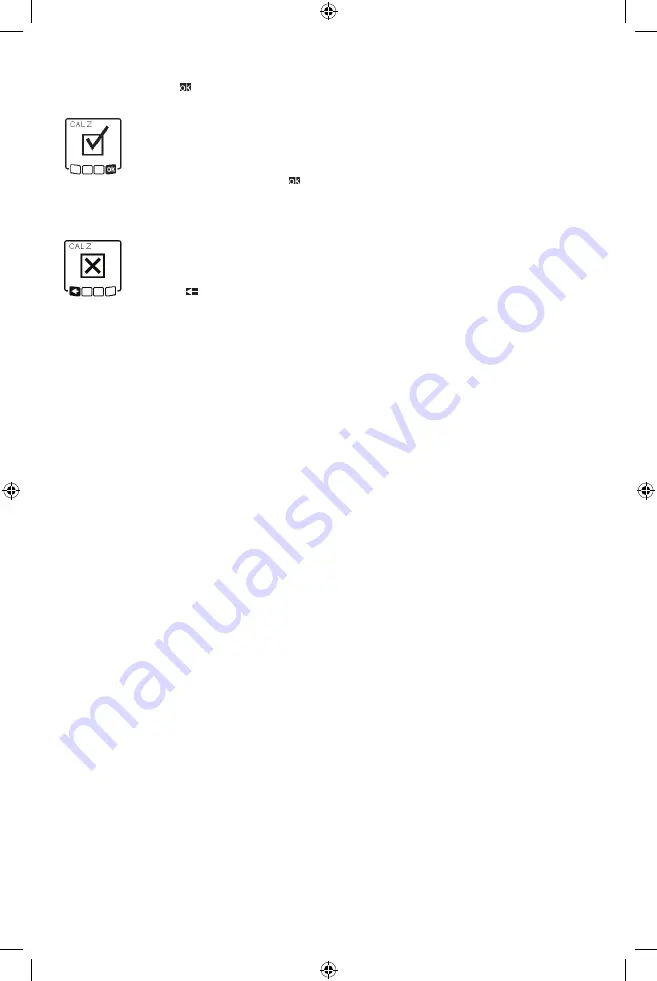
This symbol confirms that the Z-
axis has been calibrated success-
fully. At the same time, the status
indicator (12) will flash green
three times. End the calibration with by
pressing the slope button (14). If the calibra-
tion has been completed successfully, the la-
ser level then automatically switches itself off.
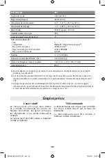
This error message will appear if
calibration of the Z-axis has been
unsuccessful. Cancel the calibra-
tion with by pressing the but-
ton for line operation (5).
Ensure that the reference vertical line is in
the pivoting range of the rotation head and
restart the calibration. Make sure that the la-
ser level is not moved during the calibration.
If the calibration is again unsuccessful, have
the laser level checked by a Bosch customer
service agent.
Working Advice
u
Only the center of the laser point or laser
line must be used for marking. The size of
the laser point/the width of the laser line
changes depending on the distance.
u
The laser level is equipped with a wireless
interface. Local operating restrictions,
e.g. in airplanes or hospitals, must be ob-
served.
Working with the Laser Target Plate
The laser target plate (53) improves visibility
of the laser beam in unfavorable conditions
and at greater distances.
The reflective surface of the laser target plate
(53) improves visibility of the laser line. The
transparent surface enables the laser line to
be seen from behind the laser target plate.
Working with the Tripod (Accessory)
A tripod offers a stable, height-adjustable
support surface for measuring. For horizontal
operation, place the laser level with the 5/8”
tripod mount (18) on the thread of the tripod
(44). Tighten the laser level using the locking
screw of the tripod.
For vertical operation, use the 5/8” tripod
mount (20).
On a tripod featuring a measuring scale on
its extender, you can set the height deviation
straight away.
Roughly align the tripod before switching on
the laser level.
Laser Goggles (Accessory)
The laser goggles filter out ambient light. This
makes the light of the laser appear brighter
to the eye.
u
Do not use the laser goggles as protective
goggles. The laser goggles make the laser
beam easier to see; they do not protect you
against laser radiation.
u
Do not use the laser goggles as sunglasses
or while driving. The laser goggles do not
provide full UV protection and impair your
ability to see colors.
Working with a wall mount and alignment
unit (see figure D)
The laser level can be secured to the wall us-
ing the wall mount with the alignment unit
(45). Using the wall mount is recommended,
e.g. when working above the maximum exten-
sion height of tripods, or when working on
unstable surfaces without a tripod.
Fasten the wall mount (45) either to a wall us-
ing screws through the fixing holes (47) or to
a strip of wall using the fastening screw. (46)
Fit the wall mount as vertical as possible to
the wall and ensure it is mounted in a stable
way.
Screw the 5/8” wall mount screw (50) into
the horizontal tripod mount (18), depending
on the requirements of the task, or the verti-
cal tripod mount (20) on the laser level.
Using the alignment unit allows the laser level
to be moved in a range of approx. 13 cm with
respect to height. Press the button (48) and
move the alignment unit to roughly the re-
quired height. It is possible to align the laser
beam precisely to a reference height using the
fine adjustment screw (49).
Working with the measuring rod
(accessory) (see figure E)
To check levels or apply slopes, it is recom-
mended to use the measuring rod (43) togeth-
er with the laser receiver.
A relative measuring scale is incorporated at
the top of the measuring rod (43). You can
preselect its zero at the bottom on the ex-
tender. This enables you to read deviations
from the target height straight away.
GRL4000-90CHVG 10-21.indd 31
10/20/21 3:24 PM


