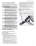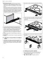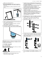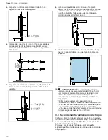
background image

Installation procedure

 en-us

15

4.

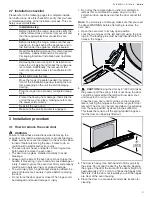
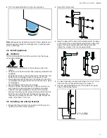
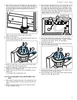
Mount strain relief (not provided with range) through the

hole of the metal plate in the back panel located below

the terminal block and secure tightly. Route the wires of

the power supply cable through the strain relief and

tighten clamp.

Make sure the strain relief is secured properly.

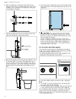
5.

Insert the flat washer.

6.

Attach the red wire to the left junction block terminal us-

ing one of the hexagonal nuts.

7.

Attach the white wire to the center junction block termi-

nal using one of the hexagonal nuts.

8.

Attach the black wire to the right junction block terminal

using one of the hexagonal nuts.

9.

Tighten all connections securely and replace terminal

block cover.
Do not plug in the range at this time.

3.10 Connecting the four-wire flexible con-

duit

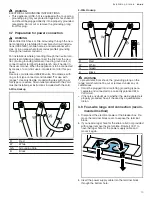
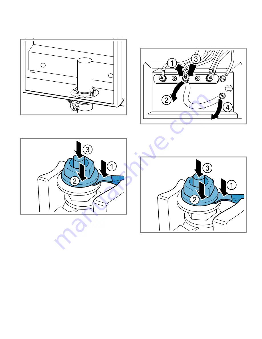
1.

Disconnect the electrical power at the breaker box. Re-

move the terminal block cover to expose the terminal

block.

2.

Insert the power supply cable into the terminal block

through the bottom hole.

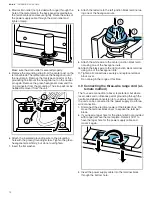
3.

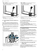
Remove the grounding strap from the center post on the

terminal block. Therefore remove the hexagonal nut of

the neutral pin. Remove the fork type connector of the

groundling link. Mount the hexagonal nut on the neutral

pin again. Remove the green hexagonal screw and the

ring connector from the grounding. The strap will not be

needed. Remove it from the unit.

4.

Attach the insulated grounding wire to the grounding

hole with the green grounding screw. Tighten the green

hexagonal screw firmly, but do not overtighten.

5.

Insert the flat washer.

6.

Attach the red wire to the left junction block terminal us-

ing one of the hexagonal nuts.

7.

Attach the white wire to the center junction block termi-

nal using one of the hexagonal nuts.

8.

Attach the black wire to the right junction block terminal

using one of the hexagonal nuts.

Summary of Contents for HIS8055C

Page 1: ...nd join the Bosch family of perks bosch home com us mybosch Free standing range HIS8055U HIS8055C HIS8655U HIS8655C en us Installation Instructions Free standing range 2 fr ca Instructions d installation Cuisinière amovible 20 ...

Page 2: ...et requirements 8 2 7 Installation checklist 9 3 Installation procedure 9 3 1 How to remove the oven door 9 3 2 Fitting the rear vent trim 10 3 3 Fitting the adjustable feet 10 3 4 Install appliance 11 3 5 Installing the anti tip bracket 11 3 6 Connect electrical supply 12 3 7 Preparation for power connection 13 3 8 Four wire range cord connection recommended method 13 3 9 Connecting the three wir...

Page 3: ...rt damage do not plug it in WARNING If the information in this manual is not followed exactly fire or shock may result causing property damage or personal injury Do not repair replace or remove any part of the appliance unless specifically recommended in the manuals Im proper installation service or maintenance can cause in jury or property damage Refer to this manual for guidance All other servic...

Page 4: ... owner the location of the circuit breaker or fuse Mark it for easy reference If required by the National Electrical Code or Canadian Electrical Code this appliance must be installed on a separate branch circuit Local codes vary The installer is responsible for ensur ing that the installation connections and grounding comply with all applicable codes The manufacturer is not responsible for any iss...

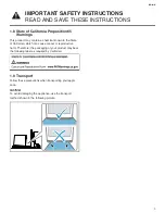
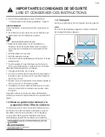
Page 5: ...r or reproductive harm Therefore the packaging of your product may bear the following label as required by California 1 9 Transport Follow these precautions when transporting your appli ance NOTICE To avoid damaging the appliance use the transport method shown in the following picture IMPORTANT SAFETY INSTRUCTIONS READ AND SAVE THESE INSTRUCTIONS ...

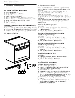
Page 6: ...el number E Nr You can find out which accessories are available for your appliance in our online shop or from our Customer Ser vice Side panel extension Use Side cover for appliances without adjacent kitchen units Order number HEZ9YZ04UC Toe kick plate for 30 appliances Use Toe kick plate to conceal the appliance feet Order number HEZ9TK30UC Toe kick plate for 36 appliances Use Toe kick plate to c...

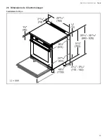
Page 7: ...Before you begin en us 7 2 5 Appliance dimensions 30 Ranges ...

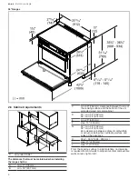
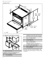
Page 8: ...ttom of the un protected wood or metal cabinet D 30 min 30 762 mm 36 min 36 914 mm E min 25 635 mm F max 13 330 mm G 30 min 30 762 mm 36 min 36 914 mm Zero clearance between adjacent combustible construction below the countertop surface and sides of the appliance H 35 36 898 930 mm I max 11 279 mm J max 7 178 mm From the cooking surface to side materials no clearance is required from unit walls to...

Page 9: ...oven door is heavy and parts of it are fragile Use both hands to remove the oven door The door front is glass Handle it carefully to avoid breakage Grasp only the side of the oven door Do not grasp the handle It may swing in your hand and cause damage or injury Failure to grasp the oven door firmly and properly could result in personal injury or product damage To avoid injury from hinge bracket sn...

Page 10: ...ews removed in the previous step 4 Take the screws from the attached bag and insert and tighten them from below 3 3 Fitting the adjustable feet 1 Remove all parts that are not permanently fixed espe cially the pan supports and burners 2 CAUTION Protect the floor Remove the accessories from the oven 3 CAUTION Do not use the door handle or project ing control panel for carrying Tilt the appliance an...

Page 11: ...ns for details Failure to follow the instructions in this manual can re sult in death or serious burns to children and adults Check for proper installation and use of the anti tip bracket Carefully tip the range forward pulling from the back to ensure that the anti tip bracket engages the range leg and prevents tip over The range should not move more than 1 2 5 cm 3 5 Installing the anti tip brack...

Page 12: ...ot remove or tamper with standoffs due to po tential temperature issues Check for proper installation and use of the anti tip bracket Carefully tip the range forward pulling from the back to ensure that the anti tip bracket engages the range leg and prevents tip over The range should not move more than 1 2 5 cm 3 6 Connect electrical supply This dual fuel range may be connected using an electric r...

Page 13: ... kits rated 208 240 volts 50 amperes with ring or fork type connector and labelled For use with ranges Use only flexible conduit with wires with ring or fork type connectors Strain relief provided with the cord must be installed per instructions included with the cord 3 Wire Hookup R Red W White GS Grounding Strip B Black 4 Wire Hookup R Red W White G Green B Black WARNING To prevent electrical sh...

Page 14: ...Attach the red wire to the left junction block terminal us ing one of the hexagonal nuts 9 Attach the white wire to the center junction block termi nal using one of the hexagonal nuts 10 Attach the black wire to the right junction block terminal using one of the hexagonal nuts 11 Tighten all connections securely and replace terminal block cover Do not plug in the range at this time 3 9 Connecting ...

Page 15: ... electrical power at the breaker box Re move the terminal block cover to expose the terminal block 2 Insert the power supply cable into the terminal block through the bottom hole 3 Remove the grounding strap from the center post on the terminal block Therefore remove the hexagonal nut of the neutral pin Remove the fork type connector of the groundling link Mount the hexagonal nut on the neutral pi...

Page 16: ... replace terminal block cover Do not plug in the range at this time 3 12 Testing the operation Check if your unit is working properly after you have com pleted the installation steps 1 Turn on power at the breaker 2 To test the oven select the bake mode See the User Manual for detailed operating instructions 3 Verify that the oven light comes on and the oven begins to preheat Customer Service 4 Cu...

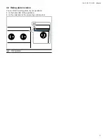
Page 17: ...Customer Service en us 17 4 2 Rating plate location You can find the rating plate of your appliance on the back side of the appliance on the underside of the projecting control panel Rating plate ...

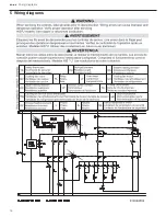
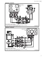
Page 18: ...en us Wiring diagrams 18 Wiring diagrams 5 Wiring diagrams Wiring diagrams ...

Page 19: ...Wiring diagrams en us 19 ...

Page 20: ...iste de contrôle pour l installation 27 3 Procédure d installation 27 3 1 Comment retirer la porte du four 27 3 2 Ajustement de la garniture de ventilation arrière 28 3 3 Montage des pieds réglables 28 3 4 Installer l appareil 29 3 5 Montage de la console anti basculement 29 3 6 Raccordement à l alimentation électrique 30 3 7 Préparation à la connexion électrique 31 3 8 Liaison par cordon à quatre...

Page 21: ...VER CES INSTRUCTIONS POUR RÉFÉRENCE FUTURE INSTALLATEUR LAISSEZ CES INSTRUCTIONS AVEC L APPAREIL UNE FOIS L INSTALLATION COMPLÈTE Examinez l appareil après l avoir déballé En cas de dommage en cours de transport ne branchez pas l appareil AVERTISSEMENT Si les consignes du présent manuel ne sont pas suivies à la lettre il y a un risque d incendie ou d électrocution pouvant entraîner des dommages ma...

Page 22: ...llation Pour éliminer le risque de brûlure ou d incendie lorsque vous vous étirez au dessus des surfaces chauffantes de l électroménager il faut éviter d installer des armoires de rangement au dessus de la surface de l électroménager Si une armoire de rangement est installé il est possible de réduire le risque en installant une hotte qui dépasse horizontalement d au moins 5 po 12 7 mm le bord du f...

Page 23: ...lectrique en fournissant une voie sûre pour le courant électrique en cas de court circuit Assurez vous que l appareil est correctement installé et mis à la terre par un technicien qualifié L installation les raccordements électriques et la mise à la terre doivent être conformes avec tous les codes en vigueur Avant de mettre sous tension la source d alimentation vérifiez que toutes les commandes so...

Page 24: ...l dans la boutique en ligne ou auprès du service client Côté d extension du panneau Utilisation Couvercle latéral pour appareils sans éléments de cuisine adjacents Numéro de commande HEZ9YZ04UC Bordure inférieure de protection pour les électroménagers de 30 po Utilisation Bordure inférieure pour dissimuler les pieds de l appareil Numéro de commande HEZ9TK30UC Bordure inférieure de protection pour ...

Page 25: ...Avant de commencer fr ca 25 2 5 Dimensions de l électroménager Cuisinières de 30 po ...

Page 26: ...armoire en bois ou en métal non protégée D 30 po min 30 po 762 mm 36 po min 36 po 914 mm E min 25 po 635 mm F max 13 po 330 mm G 30 po min 30 po 762 mm 36 po min 36 po 914 mm Dégagement nul entre la construction de combustible adjacente en dessous de la surface du comptoir et les côtés de l appareil H 35 po 36 po 898 930 mm I max 11 po 279 mm J max 7 po 178 mm De la surface de cuisson aux matériau...

Page 27: ... déplacée Procédure d installation 3 Procédure d installation Procédure d installation 3 1 Comment retirer la porte du four AVERTISSEMENT Le non respect de ces instructions lors du retrait de la porte du four peut entraîner des blessures ou endommager le produit Avant de démonter la porte s assurer que le four soit froid et que le courant qui l alimente a été coupé Le non respect de cette précauti...

Page 28: ...19 mm vers le haut pour décrocher les charnières des fentes Tirez la porte vers vous jusqu à ce que les charnières soient dégagées du boîtier du four 5 Placez la porte dans un endroit pratique et stable pour le nettoyage 6 Replacez la porte dans l ordre inverse dans lequel elle a été retirée 3 2 Ajustement de la garniture de ventilation arrière 1 La garniture de ventilation arrière est imbriquée d...

Page 29: ...Assurez vous que le dispositif anti bascule est réengagé lorsque la cuisinière est déplacée Réengager le dispositif anti basculement si la cuisinière est déplacée Ne pas utiliser la cuisinière sans le dispositif anti bascule en place et engagé Voir les instructions d installation pour plus de détails Non respect des instructions de ce manuel peut entraîner la mort ou des brûlures graves pour les e...

Page 30: ...e fixée à l arrière de l appareil 10 AVERTISSEMENT La garniture de ventilation arrière présente des espacements de 3 16 po 5 mm pour maintenir l appareil légèrement éloigné du mur arrière Ne retirez pas ou ne modifiez pas les espacements en raison de problèmes potentiels de température Vérifiez que le support anti basculement est correctement installé et utilisé Inclinez délicatement la cuisinière...

Page 31: ... la mise à la terre via le conducteur neutre Les installations pour lesquelles la mise à la terre via le conducteur neutre est interdite a déconnectez la liaison du neutre b utilisez la borne de mise à la terre ou le conducteur de dérivation du neutre c connectez la borne du neutre au conducteur de dérivation du neutre de façon habituelle Lorsque l appareil est connecté grâce à d une trousse de câ...

Page 32: ...a pince Assurez vous que la décharge de traction est correctement fixée 5 Retirez la barrette de mise à la terre du poteau central du bornier Retirez ainsi l écrou hexagonal de la broche neutre Retirez le connecteur de type fourche de la liaison de mise à la terre Remontez l écrou hexagonal sur la broche neutre Retirez la vis hexagonale verte et le raccord annulaire de la prise de terre La sangle ...

Page 33: ...décharge de traction est correctement fixée 5 Insérez la rondelle plate 6 Fixez le fil rouge à la borne gauche du bloc de raccordement à l aide d un des écrous hexagonaux 7 Fixez le fil blanc à la borne centrale du bloc de raccordement à l aide d un des écrous hexagonaux 8 Raccordez le fil noir à la borne droite du bloc de raccordement à l aide d un des écrous hexagonaux 9 Vissez bien tous les rac...

Page 34: ...au du boîtier des disjoncteurs Retirez le couvercle du bornier pour mettre le bornier à découvert 2 Insérez le câble d alimentation électrique dans le bornier en le faisant passer par le trou inférieur 3 Insérez la rondelle plate 4 Fixez le fil rouge à la borne gauche du bloc de raccordement à l aide d un des écrous hexagonaux 5 Fixez le fil blanc à la borne centrale du bloc de raccordement à l ai...

Page 35: ...iquez le numéro de modèle E Nr et le numéro de fabrication FD de l appareil USA 1 800 944 2904 www bosch home com us owner support get support www bosch home com us shop CA 1 800 944 2904 www bosch home ca en service get support www bosch home ca en service cleaners and accessories 4 1 Numéro de modèle E Nr et numéro de fabrication FD Le numéro de modèle E Nr et le numéro de fabrication FD sont in...

Page 36: ...fr ca Schémas de branchement 36 Schémas de branchement 5 Schémas de branchement Schémas de branchement ...

Page 37: ...Schémas de branchement fr ca 37 ...

Page 38: ......

Page 39: ......

Page 40: ...so on mobile phones www bosch home com welcome Looking for help You ll find it here Expert advice for your Bosch home appliances help with problems or a repair from Bosch experts Find out everything about the many ways Bosch can support you www bosch home com service Contact data of all countries are listed in the attached service directory BSH Home Appliances Corporation 1901 Main Street Suite 60...

Reviews: