EN
| 6
Bosch Security Systems | 12 August 2005
HSG9583 Series
|
Instruction Manual
|
Installation
4
INSTALLATION
CAUTION: These units must be properly
and securely mounted to a supporting
structure capable of sustaining the unit
weight. Use care when selecting mounts or
pan/tilts (not supplied) for installation; the
mounting surface and unit's weight should be
carefully considered.
4.1
Tools Required
•
Small flat blade screwdriver
•
Phillips screwdriver (#1)
•
Adjustable wrench
•
Wire cutter/stripper/crimper tool
4.2
Cable Requirements
Video Transmission (Coaxial)
Cable Type:
RG-59/U for runs < 300m (1000ft)
RG-11/U for runs < 600m (2000ft)
Cable Size:
Outside diameter between
4.6mm (0.181in)-7.9mm (0.312in)
Cable Shape:
Round
Shield:
> 93% Braided copper shield
Center Conductor:
Stranded copper center
DC Resistance:
< 15
Ω
/1000 (RG-59/U)
< 6
Ω
/1000 (RG-11/U)
Cable Impedence:
75
Ω
Agency Rating:
UL
Environmental:
Outdoor rated
Temperature Rating: > 80°C
Sources:
Belden 9259
Input Power Cord - North American
Cable Type:
SJTOW rated
Cable Size:
Outside diameter between
4.3mm (0.170in)-11.9mm (0.470in)
Cable Shape:
Round
Conductors:
3-conductor version and
2-conductor version
Agency Rating:
UL/C.S.A., UL VW-1
Environmental:
Outdoor rated
Temperature Rating: 105°C
Voltage Rating:
300 V
Sources:
Belden 19509, 3-conductor
Northwire FSJT183-81K, 3-conductor
Input Power Cord - European
Cable Type:
H05RN-F 3 G 0.75 and
H05RN-F 3 G 1.00
Cable Size:
Outside diameter between
4.3mm (0.170in)-11.9mm (0.470in)
Cable Shape:
Round
Conductors:
3-conductor version and
2-conductor version
Agency Rating:
VDE
Environmental:
Outdoor rated
Sources:
Olflex rubber cable 1600 252
Olflex rubber cable 1600 253
Lens Control Cable
Cable Type:
Jacketed multiconductor cable
Cable Size:
Outside diameter between
4.3mm (0.170in)-11.9mm (0.470in)
Cable Shape:
Round
Shield:
Overall shielding
Conductors:
Stranded 20 to 16AWG wire
No. of Conductors:
4 and 8
Conductor Insulation: Color coded
Sources:
Belden 9552, 4-conductor
Belden 9554, 8-conductor
4.3
Housing Mounting
1.
Use the two 1/4-20 x 0.50in. screws and
1/4in. spring washers provided in the hardware
kit to mount the housing to a mount or a
pan/tilt. The spring washers must be used for
the screws to thread properly.
2.
The outermost set of 1/4-20 threaded holes are
for mounting to feed-through mounts and the
innermost 1/4-20 holes are for mounting to all
other mounts and pan/tilts.
4.4
Opening the Cover
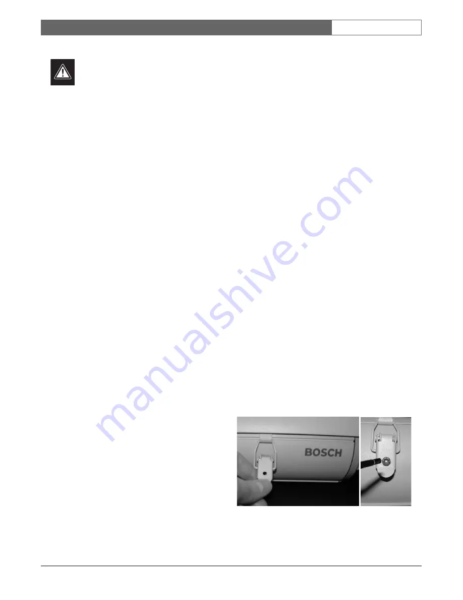
1.
Open the cover by unlatching the two clasps
on the side of the housing (see FIGURE 1).
Figure 1: Unlatching the Cover
NOTE: If the optional tamper-resistant screws have
been installed, use the supplied wrench to
remove the screws before opening the latches.
Summary of Contents for HSG9583 Series
Page 14: ...HSG9583 Series Instruction Manual EN 14 Bosch Security Systems 12 August 2005 ...
Page 28: ...Série HSG9583 Manuel d utilisation FR 14 Bosch Security Systems 12 August 2005 ...
Page 54: ...Serie HSG9583 Manual de instrucciones ES 14 Bosch Security Systems 12 August 2005 ...
Page 91: ...Série HSG9583 Manual de Instrução PT 13 Bosch Security Systems 12 August 2005 ...


