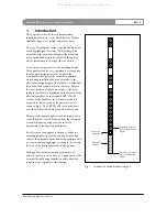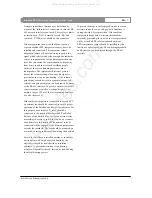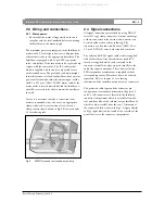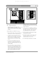
Although in terms of safety and immunity this is the
most preferable set up, an unwanted ground loop is
created which can cause audible noise or hum. The
appearance of this effect is strongly depending on the
cable routing, the design of the grounding scheme and
the existence of local magnetic fields (caused by power
transformers, railway chopper supplies etc.). If a
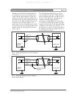
ground loop occurs, the most straight forward solution
to the problem is to interrupt the ground path from the
shielding of the audio signal wiring. This situation is
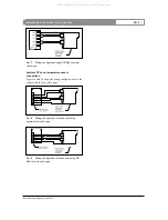
shown in Fig 10.
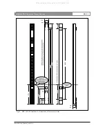
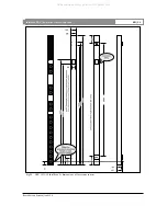
Fig 10
Grounding configuration with totally decoupled
audio ground
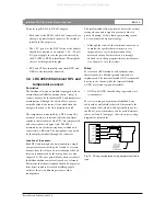
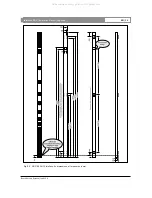
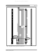
Fig 11
Grounding configuration with low frequency
decoupled audio ground
The audio input transformers feature a very high
Common Mode Rejection Ratio (CMRR), this means
that an interfering signal which is coupled onto both
the audio + and - signal wires is strongly rejected
compared to the differential audio signal.
Unfortunately, this high CMRR is only achieved at
low frequencies (<100 Hz) and deteriorates for higher
frequencies. In order to restore the original grounding
configuration for the HF part of the spectrum, it is
good a practice to connect a 100 nF capacitor between
the shielding of the audio cable and the GND pin of
the terminal block (see Fig 11).
Intellivox DDC |
Installation Manual
|
Appendix
Bosch Security Systems | July 2003
EN
| 15
All manuals and user guides at all-guides.com


