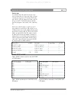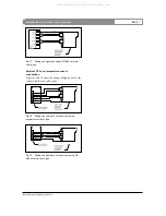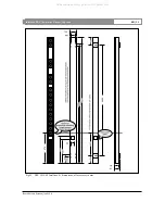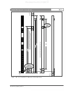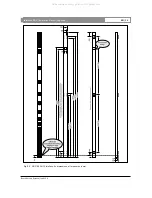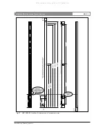
Notes for type RS-232 to RS-485 adapter:
•
Both ends of the RS-232 to RS-485 connector have
the same 9p female sub-d connector. Be careful to
install it in the proper way.
•
The +9 V (pin 9) at the RS-232 side of the adapter
should be connected to an ex 9 V / 50 mA
DC power supply in case the power delivered by
the PC (RTS or DTR) is insufficient. This might be
the case with large cable lengths.
•
RTS and CTS are internally connected, DTR and
DSR are also internally connected.
3.4 LBC 3262/00 Ambient SPL and
temperature sensor.
Description.
The Intellivox electronics module is equipped with an
external terminal (labeled ambient noise / temp) to
connect a sensor for the ambient SPL and temperature
measurement. Although the unit is able to operate
normally without the sensor, it is needed when the
auto gain function or the frost protection is used.
The temperature is measured by a NTC resistor. By
means of a software correction table the non-linear
resistance characteristics of the NTC are compensated
and converted into a degree scale. The SPL is
measured by an electret microphone, rectified and
converted to a dB scale. The microphone is powered
by the amplifier module through the connector.
Location of the sensor.
Both NTC and microphone are mounted in a single
compact enclosure which can be located at a certain
distance from the column. In most situations the best
location is determined by the microphone (see also
chapter 2.2). The auto gain will only work correctly if
the diffuse ambient noise level is used as a reference.
This means that the microphone should be kept away
from direct sound sources such as talking people,
outlets of the air conditioning system or other
loudspeakers.
The implemented software protocol freezes the volume
setting when an audio signal is present in order to
prevent ‘hunting’ of the column’s gain setting caused
by its own radiated acoustical energy.
•
Although the circuit of the combined sensor is not
complex, the specific characteristics are very
important for a correct interpretation of the
measured values. For this reason it is strongly
advised to use the appropriate factory tested sensor
(see chapter 3.1 for order codes).
Wiring.
For reasons of RFI immunity and optimum noise
characteristics two different ground terminals are
implemented. The terminal labeled GND is connected
directly to the chassis, while the terminals labeled
AGND are reference ground terminals.
•
GND and AGND should be kept apart under all
circumstances!
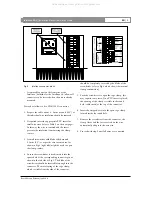
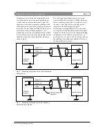
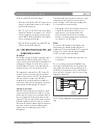
For correct wiring an asymmetrical shielded 2 way
cable with overall shield is advised. Alternatively the
twin twisted cable, which is also optionally in use for
the RS-485 network interface, can be used. Reference
source not found. (next page) show the correct wiring
diagram for both cables.
Fig 16
Wiring configuration using asymmetrical cable
type
Intellivox DDC |
Installation Manual
|
Appendix
Bosch Security Systems | July 2003
EN
| 20
All manuals and user guides at all-guides.com


