background image

2.

Installation guide

This chapter deals with the practical aspects of
installing the Intellivox loudspeaker column. 

SI units are used as a default, all mentioned
dimensions are stated in meters or millimeters. 

Unless stated otherwise, column dimensions refer to
the standard Intellivox-2c, which has the electronics
module mounted at the low end of the enclosure.
Dimensions of other Intellivox models can be taken
from the appropriate datasheet.

2.1 Items in the box.

The following items are shipped with each Intellivox
column:

Table 1 List of shipped items.

The mounting brackets as well as the connector set
are packed in one of the top end boxes of the main
packaging.

2.2 General considerations.

As already mentioned, mounting height and position
are important parameters in relation to the acoustical
performance of the system. Unless specified otherwise
by the sound system designer, the Intellivox column
should be mounted in a position exactly perpendicular
to the listening plane. Contrary to a conventional ‘low
Q’ loudspeaker system, minor mechanical
misalignment may lead to a degraded coverage and
intelligibility.

Unless otherwise stated by the designer, the Intellivox
column with a-symmetrically placed transducers,
should be mounted with the ‘high frequency acoustical
center’ at the lowest position.

The Intellivox is mains powered, the mains ground
terminal should always be connected to a proper safety
ground. Other safety regulations may also require a
separate mains distribution network or an un-
interruptible mains power supply (UPS).

The Intellivox requires a signal source. For this
purpose preferably a symmetrical line level (0 dBV)
signal can be used. Alternatively the audio input can
be supplied by an existing 70V/100V network (if the
default transformer balanced input board is installed).
Refer to chapter 3.2 and chapter 2.4 for more
information.

The Intellivox is equipped with a RS-485 network
interface. This interface serves two basic purposes. The
first one is to adjust all relevant parameters (i.e. gain,
‘steering’ angle) during installation. Secondly it might
be used to integrate the Intellivox into a network for
continuous surveillance and ‘on line’ control. In cases
where these last mentioned network options are not
required, the RS-485 wiring can be omitted. One
should however realize that the existence of network
wiring greatly simplifies the transfer of the initial
parameters as well as any future DSP software
upgrades or functional check-ups, especially in
situations where a unit is located on a position which is
hardly accessible. Refer to chapter 3.3 for more
information about the RS-485 network. 

If more then one unit has to be connected to the RS-
485 RS-485 network network, make sure that every
unit is set to a unique network address before
connecting to the RS-485 network. The network
address can be changed by connecting the individual
device via an RS-232 to RS-485 adapter to a host PC
running WinControl the appropriate software. More
information can be found in the help file of
WinControl.

Intellivox DDC | 

Installation Manual

Installation Guide

Bosch Security Systems | July 2003 

EN

| 6

Description

Pieces

Mounting brackets

2

IEC 3p female mains connector (cable
socket)

1

WAGO series 231 6p input signal connector
(cable socket with strain relief housing)

1

WAGO series 231 5p RS485 signal connector
(cable socket with strain relief housing)

1

PVC inserts for WAGO connectors (for 3
different wire sizes)

1 x 5
2 x 2 x 5

Wire insertion tool for WAGO cage
clamp connector

1

All manuals and user guides at all-guides.com

Summary of Contents for INTELLIVOX DDC LBC 325 Series

Page 1: ...INTELLIVOX DDC Installation Manual EN Active Line Array Loudspeakers LBC 325x Series All manuals and user guides at all guides com a l l g u i d e s c o m ...

Page 2: ...leaners but a damp cloth 6 Protect the product from overheating Do not block ventilation slots The product should not be built in unless proper ventilation is provided 7 The purchaser should not attempt to service the product as he or she may be exposed to dangerous voltages All maintenance and service should be carried out by Bosch Security Systems or its authorized agents Bosch Security Systems ...

Page 3: ... network cable to the unit 18 Fig 16 Wiring configuration using asymmetrical cable type 20 Fig 17 Wiring configuration using RS 485 network cable type 21 Fig 18 Wiring configuration at the sensor using asymmetrical cable type 21 Fig 19 Wiring configuration at the sensor using RS 485 network cable type 21 Fig 20 LBC 3251 00 Intellivox 1b dimensions all measures in mm 22 Fig 21 LBC 3252 00 Intellivo...

Page 4: ... the location of the electronics module In the standard LBC 325x 00 versions of the Intellivox the electronics module is mounted in the lower end of the enclosure as it is shown in Fig 1 The LBC 325x 10 versions however have the electronics module mounted at the top end Because of the extreme tight vertical radiation pattern of the Intellivox a small deviation from the calculated acoustical mounti...

Page 5: ...y the audio input can be supplied by an existing 70V 100V network if the default transformer balanced input board is installed Refer to chapter 3 2 and chapter 2 4 for more information The Intellivox is equipped with a RS 485 network interface This interface serves two basic purposes The first one is to adjust all relevant parameters i e gain steering angle during installation Secondly it might be...

Page 6: ...d be connected to ensure proper operation of the Intellivox under all circumstances For this purpose an external 24 V relay should be connected to the terminal block marked Fan Relay Because of the limited drive current an external relay must always be used to switch the fan do not connect a fan directly to this terminal The external relay if connected will be engaged if the heatsink temperature e...

Page 7: ...ections All signal connections are realized by using WAGO series 231 cage clamp connectors A major advantage of these connectors is the fact that the connector can be fitted without the need for soldering The connectors can be used with 0 08 mm2 AWG 28 to 2 5 mm2 AWG 12 wires both stranded or massive The audio and RS 485 signal cable socket is supplied with the Intellivox Also three different size...

Page 8: ...e hole of the corresponding connector pin as shown in the left side of Fig 5 The blade of the screwdriver should be inserted far enough into the connector The metal spring of the cage clamp which is visible from the side of the connector should be completely covered by the blade of the screwdriver refer to Fig 4 which shows the internal clamp construction 5 Push the screwdriver to open the cage cl...

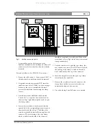
Page 9: ...al wall brackets The brackets are supplied with each Intellivox and come in the same color as the enclosure A technical drawing of the bracket is shown in Fig 6 The brackets allow mounting of the Intellivox on a straight wall or on a curved surface pillar while keeping a distance of 25 mm 1 0 between the rear of the enclosure and the wall Refer to chapter 2 5 3 for the standard mounting procedure ...

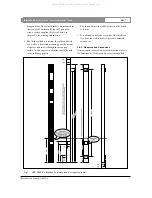
Page 10: ...ntion should be paid to the following aspects The threaded inserts are M5 metric and the depth is 16 mm It is advised to keep the rear side of the Intellivox free from the wall in order to prevent unwanted resonances 2 5 2 Measures and dimensions As mentioned earlier all enclosure dimensions refer to the Intellivox 2c Other models or custom supplied Intellivox DDC Installation Manual Installation ...

Page 11: ... possible to slide the bracket over the heads Check this with a bracket before mounting it to the column 4 Check if the chosen mounting holes ensure that the final position of the column will be in the vertical angle that is specified which is usually exactly perpendicular to the listening area Use extra spacers if necessary 5 Remove the front grill s of the Intellivox before mounting the unit and...

Page 12: ...complex the RS 485 terminal of the chassis also has a DGND pin while the ambient SPL temperature terminal has both GND and AGND pins The pins labeled GND are connected directly to the chassis The RS 485 DGND pin is not a ground pin but serves as a reference for the RS 485 AB and YZ wires Although the DGND pin should be connected to the shielding of the RS 485 cable when in use DGND and ABYZ has no...

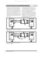
Page 13: ...ther ground pin GND or DGND on the chassis Fig 8 Ground configuration of the Intellivox chassis Fig 9 Standard grounding configuration Because safety is a very important issue the safety ground pin of the IEC mains connector should always be connected to a low impedance ground network If the standard solution is chosen to be connected the audio line level inputs the grounding situation is accordin...

Page 14: ...d audio ground Fig 11 Grounding configuration with low frequency decoupled audio ground The audio input transformers feature a very high Common Mode Rejection Ratio CMRR this means that an interfering signal which is coupled onto both the audio and signal wires is strongly rejected compared to the differential audio signal Unfortunately this high CMRR is only achieved at low frequencies 100 Hz and...

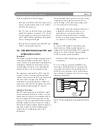
Page 15: ...escribed is also well suited for installations with multiple distributed units on one signal source If only one chassis is connected interruption of the loop near the signal source is theoretically a better option although this method can cause problems if the output of the audio source is not equipped with a transformer electronically differential output Due to the capacitive coupling of the remo...

Page 16: ... configuration chosen Fig 14 Structure of the RS 485 network 3 3 Some notes on the RS 485 network interface In order to integrate the unit in a surveillance and control network a full duplex RS 485 terminal is incorporated The RS 485 standard is chosen for the ability of driving long cables the simplicity of the network topology and high immunity to external electromagnetic fields which results in...

Page 17: ... resistance cable the maximum length specified for safe transmission is 1500 m If the distance is significantly longer a network repeater will be needed Cable termination According to the official RS 485 standard the network should be terminated with 120 OHM resistors at both ends of each pair while the length of the stub lines should not exceed 7 m The RS 485 transceivers which are implemented in...

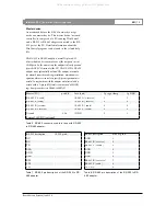
Page 18: ...ed In conjunction with the adapter a dedicated cable is needed with a 9 pin sub D female connector and a WAGO cage clamp connector see Table 6 to Table 8 Table 6 RS 485 connection cable for use with RS 232 to RS 485 adapter Table 7 RS 232 pin description of the RS 232 to RS 485 adapter Table 8 RS 485 pin description of the RS 232 to RS 485 adapter Intellivox DDC Installation Manual Appendix Bosch ...

Page 19: ...cation is determined by the microphone see also chapter 2 2 The auto gain will only work correctly if the diffuse ambient noise level is used as a reference This means that the microphone should be kept away from direct sound sources such as talking people outlets of the air conditioning system or other loudspeakers The implemented software protocol freezes the volume setting when an audio signal ...

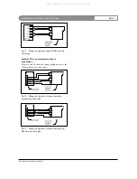
Page 20: ...iring configurations for the sensor with the two cable types Fig 18 Wiring configuration at the sensor using asymmetrical cable type Fig 19 Wiring configuration at the sensor using RS 485 network cable type Intellivox DDC Installation Manual Appendix Bosch Security Systems July 2003 EN 21 All manuals and user guides at all guides com ...

Page 21: ... different models Fig 20 LBC 3251 00 Intellivox 1b dimensions all measures in mm Intellivox DDC Installation Manual Appendix Bosch Security Systems July 2003 EN 22 All manuals and user guides at all guides com a l l g u i d e s c o m ...

Page 22: ...Fig 21 LBC 3252 00 Intellivox 2b dimensions all measures in mm Intellivox DDC Installation Manual Appendix Bosch Security Systems July 2003 EN 23 All manuals and user guides at all guides com ...

Page 23: ...Fig 22 LBC 3252 10 Intellivox 2b dimensions all measures in mm Intellivox DDC Installation Manual Appendix Bosch Security Systems July 2003 EN 24 All manuals and user guides at all guides com ...

Page 24: ...Fig 23 LBC 3253 00 Intellivox 2c dimensions all measures in mm Intellivox DDC Installation Manual Appendix Bosch Security Systems July 2003 EN 25 All manuals and user guides at all guides com ...

Page 25: ...Fig 24 LBC 3253 10 Intellivox 2c dimensions all measures in mm Intellivox DDC Installation Manual Appendix Bosch Security Systems July 2003 EN 26 All manuals and user guides at all guides com ...

Page 26: ...LBC 3254 00 Intellivox 4c dimensions all measures in mm Intellivox DDC Installation Manual Appendix Bosch Security Systems July 2003 EN 27 All manuals and user guides at all guides com a l l g u i d e s c o m ...

Page 27: ...Fig 26 LBC 3254 10 Intellivox 4c dimensions all measures in mm Intellivox DDC Installation Manual Appendix Bosch Security Systems July 2003 EN 28 All manuals and user guides at all guides com ...

Page 28: ...Fig 27 LBC 3256 00 Intellivox 6c dimensions all measures in mm Intellivox DDC Installation Manual Appendix Bosch Security Systems July 2003 EN 29 All manuals and user guides at all guides com ...

Page 29: ...Fig 28 LBC 3256 10 Intellivox 6c dimensions all measures in mm Intellivox DDC Installation Manual Appendix Bosch Security Systems July 2003 EN 30 All manuals and user guides at all guides com ...

Page 30: ... GmbH Geschäftsbereich Postfach 10 60 50 70049 Stuttgart Telefax 0711 811 12 34 www bosch de k Bosch Security Systems B V P O Box 80002 5600 JB Eindhoven The Netherlands Tele 31 40 27 80000 www boschsecuritysystems com All manuals and user guides at all guides com ...

Reviews: