2 | F01U167054-01 | 8/10
ISW-EN4200 Serial Receiver Installation Guide
©
2010 Bosch Security Systems, Inc.
3.0
Wiring Connections
Do not install long cable runs next to high-current
power feeds.
Keep cable lengths as short as possible to minimize
noise pickup.
Measure voltage at the serial receiver on long cable
runs.
To connect the ISW-EN4200 to the ISW-D8125CW-V2:
1.
Remove all power from the system (AC and standby battery).
2.
Route the cabling through either the bottom cabling knockout
or the side cabling knockout on the ISW-EN4200.
Refer to Figure 1.
3.
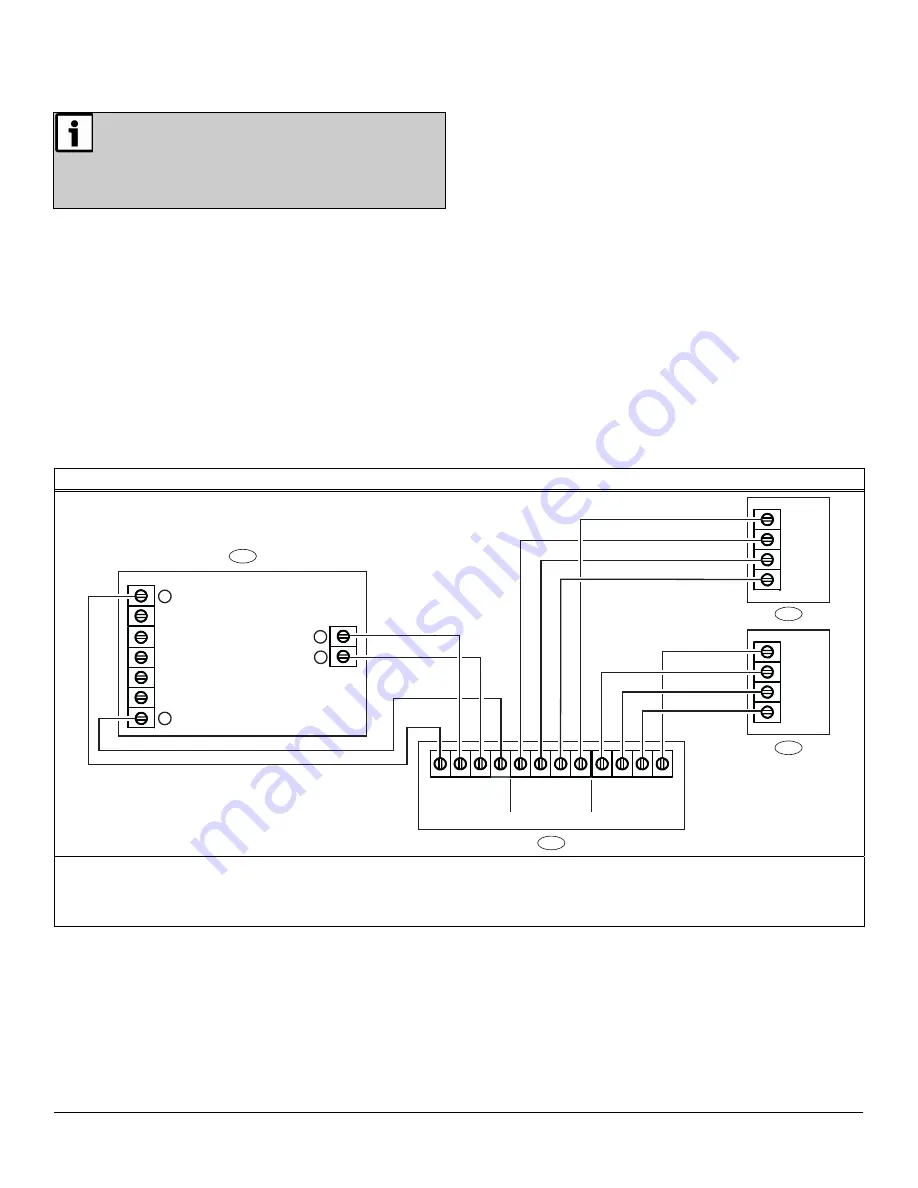
Connect the serial data terminal block on the ISW-EN4200 to
the data terminal block on the ISW-D8125CW-V2.
Refer to Figure 2 below, or Figure 3 on page 3.
Ensure that the wiring used meets the following specifications:
-
Four-conductor unshielded 20 AWG (or larger)
-
Wire length must not exceed 30.5 m (100 ft)
For UL Listed installations, install the ISW-D8125CW-V2
Commercial Wireless Interface Module within 20 ft (6 m)
of, and within the same room as, the ISW-EN4200.
4.
Connect the ISW-D8125CW-V2 to the control panel.
-
For all versions of the D7412 and D7212 Control Panels,
you can connect one ISW-D8125CW-V2 Commercial
Wireless Interface Module, and up to two ISW-EN4200
Serial Receivers. Refer to Figure 2 below.
-
For all versions of the D9412 Control Panel, and the
D9112 Control Panel, you can connect two
ISW-D8125CW-V2 Commercial Wireless Interface Modules
(one to Zonex 1 and the other to Zonex 2), and up to four
ISW-EN4200 Serial Receivers (two to each
ISW-D8125CW-V2). Refer to Figure 3 on page 3.
Figure 2: ISW-D8125CW-V2 to D7412 and D7212 (GV3, GV2, and G) Control Panel Wiring Diagram
ZONEX BUS
RECEIVER 2
RECEIVER 1
+12V
TX1
RX1
GND
+12V
IN
OUT
GND
+12V
TX2
RX2
GND
Vs
RX
TX
GND
Vs
RX
TX
GND
ZONEX OUT 1
ZONEX IN 1
27
28
2
1
3
4
3
+ AUX POWER
COMMON
9
1 -
ISW-D8125CW-V2 connected to Zonex 1 on control panel (Points 9 to 127)
2 -
Control Panel
3 -
ISW-EN4200 Receiver (RECEIVER 1 on ISW-D8125CW-V2)
4 -
ISW-EN4200 Receiver (RECEIVER 2 on ISW-D8125CW-V2)


